Thermal processing apparatus

a technology of processing apparatus and heating element, which is applied in the direction of lighting and heating apparatus, muffle furnaces, furnaces, etc., can solve the problems of troublesome cleaning and maintenance work, and achieve the effect of preventing a reduction in flow rate, extending the life of the apparatus, and double the maintenance cycl

Active Publication Date: 2010-09-28
TOKYO ELECTRON LTD
View PDF9 Cites 3 Cited by
  • Summary
  • Abstract
  • Description
  • Claims
  • Application Information

AI Technical Summary

Benefits of technology

[0011]This configuration causes the gas supplied from the supply port provided in the upper surface portion of the lid body to flow through the plurality of exhaust ports provided in the side portion of the upper surface portion of the lid body into the exhaust pipe, and be exhausted to the outside via the outlet pipe connected to the outlet provided at a point at equal distances from the exhaust ports in the exhaust pipe. Accordingly, contamination of the substrate by the impurities such as a sublimate and the like generated from the substrate thermally processed is prevented. Further, since the impurities such as a sublimate and the like flow through the plurality of exhaust ports provided in the lid body into the exhaust pipe together with the gas, and is exhausted to the outside via the outlet pipe connected to the exhaust ports provided in the exhaust pipe, the impurities hardly adhere to the inner surface of the outlet pipe. Further, if the impurities adhere to the inner surface of the exhaust pipe to clog the exhaust pipe, the exhaust pipe can be detached from the lid body and easily cleaned.
[0022]According to the present invention, contamination of the substrate due to the impurities such as a sublimate and the like generated from the substrate thermally processed can be prevented to improve the yields. Further, adherence of the impurities to the inner surface of the outlet path can be made hardly occur and the exhaust pipe to which the impurities have adhered can be detached from the lid body and cleaned, thus improving the reliability of the apparatus and facilitating the maintenance thereof.

Problems solved by technology

The technique described in Japanese Patent Application Laid-open No. 2003-318091, however, has problems.
One problem is that if a large amount of impurities such as a sublimate and the like is generated, the exhaust pipe is clogged in a short time, and therefore maintenance should be frequently performed.
Another problem is that the impurities adhere also to the current plate for exhaust, but cleaning and maintenance work is troublesome because a plurality of current plates for exhaust are provided to lose the pressure of the exhaust.

Method used


Image

  • Thermal processing apparatus
  • Thermal processing apparatus
  • Thermal processing apparatus

Examples


first embodiment

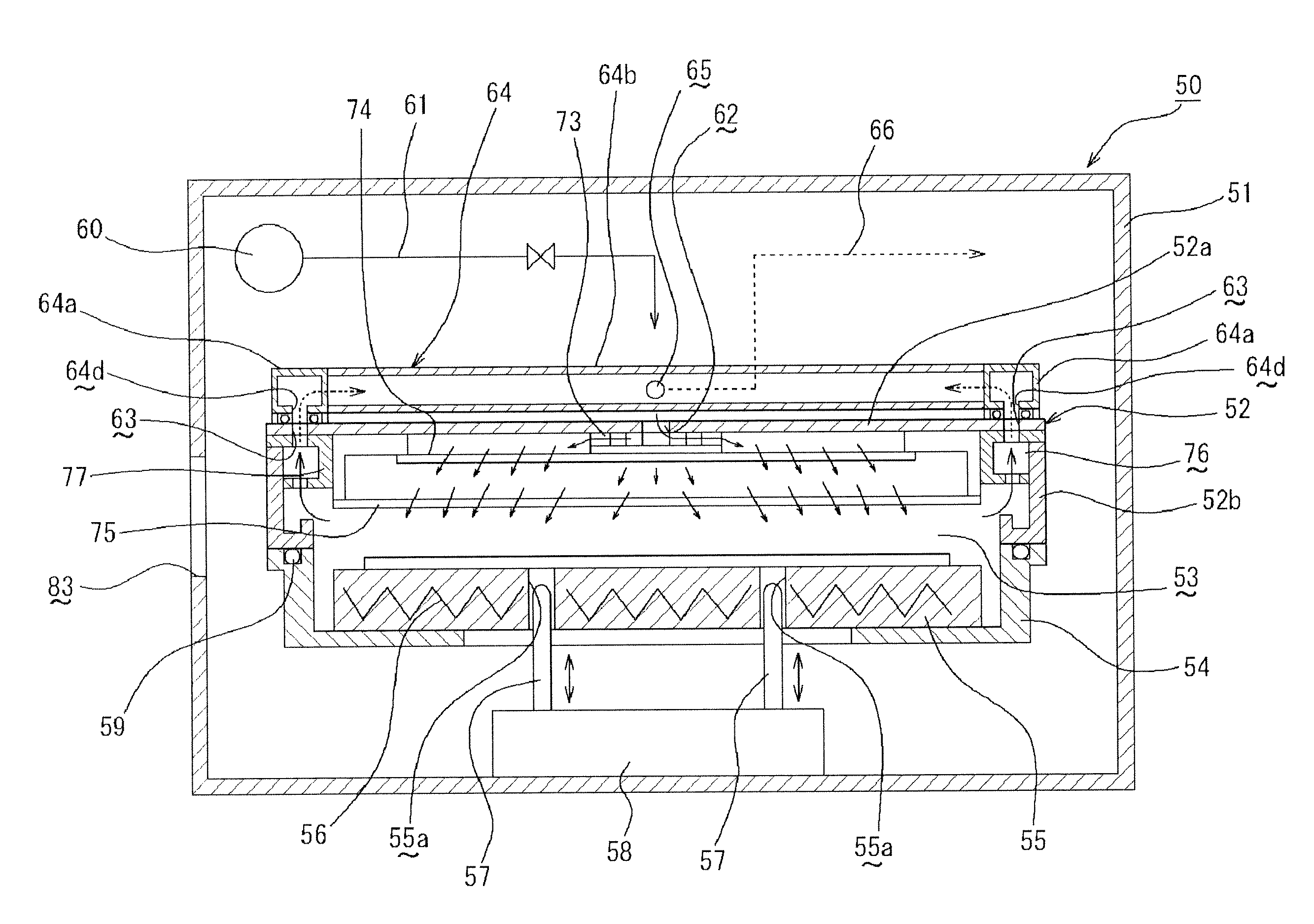
[0062]FIG. 4 is a cross-sectional view showing the usage state of a first embodiment, FIG. 5 is a plan view showing the principal part of the thermal processing apparatus, and FIG. 6 to FIG. 8 are a cross-sectional view taken along a I-I line in FIG. 5, a cross-sectional view taken along a II-II line in FIG. 5, and a cross-sectional view taken along a III-III line in FIG. 5 respectively.

[0063]A thermal processing apparatus 50 includes in a casing 51, as shown in FIG. 4, a vertically movable lid body 52, and a support ring 54 located on the lower side of the lid body 52 and constituting a processing chamber 53 in cooperation with the lid body 52.

[0064]The support ring 54 has, for example, an almost cylindrical shape with upper and lower faces open, and houses a heating plate 55 as a thermal processing plate therein. Housing the heating plate 55 closes the lower face of the support ring 54. The heating plate 55 has a thick disk shape to mount and heat the wafer W being the substrate o...

second embodiment

[0094]FIG. 14 is a schematic plan view of the principal part showing the thermal processing apparatus of a second embodiment.

[0095]The second embodiment is an embodiment to allow extension of the maintenance interval. More specifically, in the second embodiment, a first outlet 65A and a second outlet 65B are provided at the opposing side wall portions at an almost intermediate portion of the coupling pipe body 64b of the exhaust pipe 64, and corresponding first outlet pipe 66A and second outlet pipe 66B are connected to the first outlet 65A and the second outlet 65B, respectively as shown in FIG. 14. Further, a pressure sensor 90 being a clogging detection means for detecting clogging due to the impurities in the exhaust flowing through the first outlet pipe 66A is provided along the first outlet pipe 66A, and a switching valve 91 is provided along the second outlet pipe 66B. The pressure sensor 90 and the switching valve 91 are electrically connected to a control means, for example...

third embodiment

[0098]FIG. 15 is a schematic plan view of the principal part showing the thermal processing apparatus according to a third embodiment.

[0099]The third embodiment is an embodiment to improve the exhaust efficiency and prevent a reduction in flow rate due to adherence of the volatile component contained in the impurities in an exhaust fluid. More specifically, in the third embodiment, an ejector 200 being an exhauster is provided along the outlet pipe 66 at a position near the outlet 65 as shown in FIG. 15 in each of the multi-tiered thermal processing apparatuses 50. The ejector 87 provided at the dedicated hose 86 as shown in the previously illustrated FIG. 13 is not installed. The other portions are the same as those in the first embodiment, and therefore the same numerals and symbols are given to the same portions to omit their description.

[0100]According to the third embodiment having the above characteristics, drive of the ejector 200 can exhaust the gas supplied into the process...


PUM


Abstract

A thermal processing apparatus for thermally processing a substrate in a processing chamber includes a heating plate for mounting and thermally processing the substrate thereon, and a lid body covering the heating plate from above to constitute a portion of the processing chamber. The lid body has a ceiling plate and a peripheral side portion vertically provided at a peripheral end portion of the ceiling plate. The ceiling plate is provided with a supply port for supplying a gas into the processing chamber, and a side portion of the ceiling plate is provided with a plurality of exhaust ports for exhausting the gas in the processing chamber. An exhaust pipe communicating with the exhaust ports and having an outlet at a point at equal distances from the exhaust ports is provided to be attachable and detachable to / from the lid body. According to the present invention, the maintenance work against clogging due to the impurities such as a sublimate and the like generated by the thermal processing can be easily performed.

Description

BACKGROUND OF THE INVENTION[0001]1. Field of the Invention[0002]The present invention relates to a thermal processing apparatus and, more specifically, to a thermal processing apparatus for performing heat processing for a substrate, for example, a semiconductor wafer, an LCD glass substrate or the like.[0003]2. Description of the Related Art[0004]Generally, in manufacture of a semiconductor device, the photolithography technology is used to form a thin film of ITO (Indium Tin Oxide) and an electrode pattern on a semiconductor wafer, LCD glass substrate, or the like (hereinafter, referred to as a substrate). In the photolithography technology, a photoresist is applied on the wafer, a resist film formed by the application is exposed to light according to a predetermined circuit pattern, and the exposed pattern is subjected to developing treatment to form a circuit pattern in the resist film.[0005]In the photolithography process, various kinds of heat processing are performed, such as...

Claims


Application Information

Patent Timeline
Patent Type & Authority Patents(United States)
IPC IPC(8): F27D1/18
CPCH01L21/67017H01L21/67109H01L21/6719H01L21/324
Inventor OOSHIMA, KAZUHIKOAOKI, SHIGEKI
Owner TOKYO ELECTRON LTD
Why Eureka
Try Eureka