Combination of connector assembly and two printed circuit boards

a technology of printed circuit board and connector, which is applied in the direction of coupling contact member, fixed connection, coupling device connection, etc., can solve the problems of inconvenient plug connector, and achieve the effect of convenient assembly and separation of receptacle connector

Inactive Publication Date: 2010-09-28
CHENG UEI PRECISION IND CO LTD
View PDF8 Cites 44 Cited by
  • Summary
  • Abstract
  • Description
  • Claims
  • Application Information

AI Technical Summary

Benefits of technology

[0006]As described above, the guiding gap of the first printed circuit board is opened to communicate with the assisting channels of the receptacle connector, so that overcomes the shape limit of the printed circuit boards, and facilitates the assembly and the separation of the receptacle connector and the plug connector.

Problems solved by technology

As a result, the assembly and the separation of the receptacle connector and the plug connector are sometimes inconvenient because of the limit of insertion / withdrawal directions and the printed circuit board shape.

Method used


Image

  • Combination of connector assembly and two printed circuit boards
  • Combination of connector assembly and two printed circuit boards
  • Combination of connector assembly and two printed circuit boards

Examples


Embodiment Construction

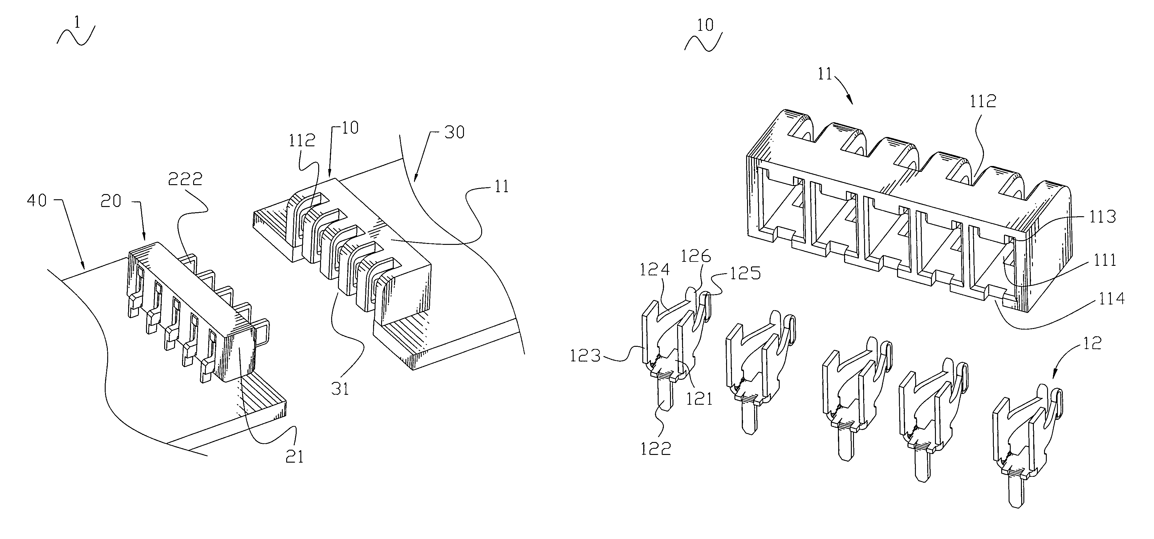
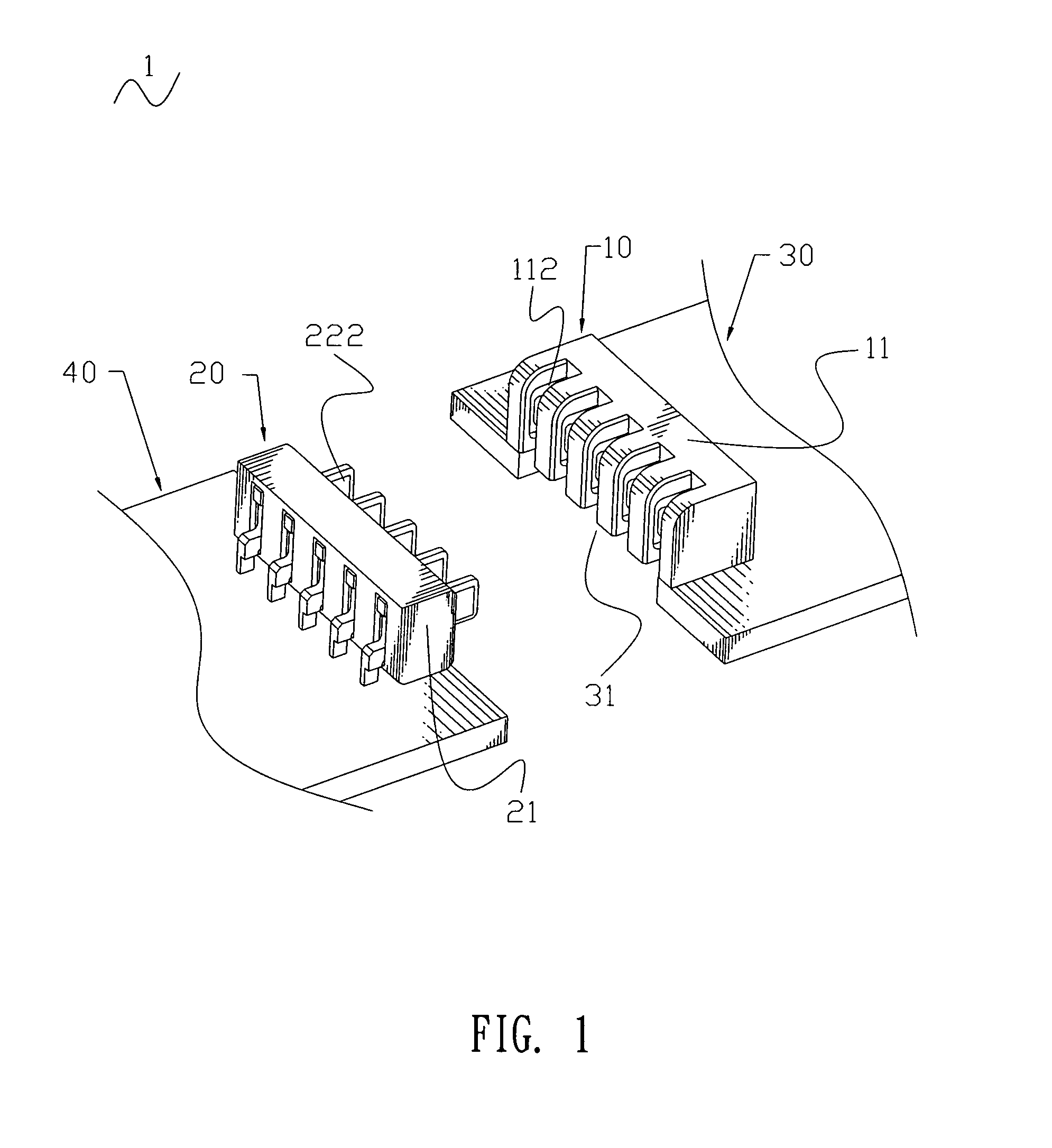
[0013]With reference to FIG. 1, a combination 1 of connector assembly and two printed circuit boards according to the present invention includes a receptacle connector 10, a plug connector 20 mated with the receptacle connector 10, a first printed circuit board 30 electrically connected with the receptacle connector 10 and a second printed circuit board 40 electrically connected with the plug connector 20.

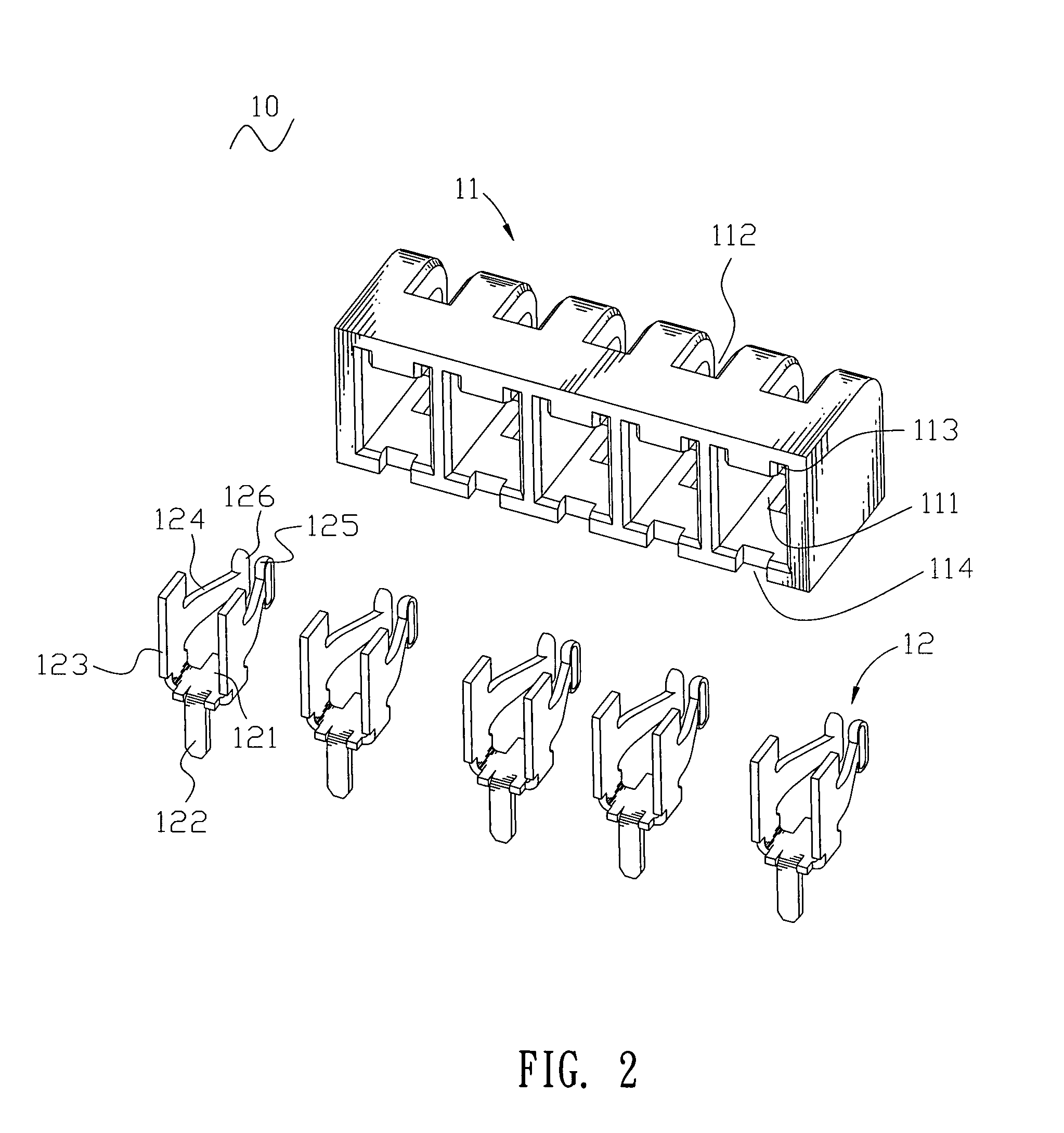
[0014]With reference to FIG. 2, the receptacle connector 10 includes a receptacle insulating housing 11 of substantially rectangular shape and a plurality of receptacle terminals 12 disposed in the receptacle insulating housing 11. The receptacle insulating housing 11 defines a plurality of rectangular receiving cavities 111 arranged at regular intervals along a longwise direction thereof and each passing through a front surface thereof. The receptacle insulating housing 11 further defines a plurality of rectangular assisting channels 112 each vertically to penetrate through a top ...


PUM


Abstract

A combination of connector assembly and two printed circuit boards includes a first printed circuit board defining a guiding gap at one edge thereof and a second printed circuit board, a receptacle connector including a receptacle insulating housing and a plurality of receptacle terminals, a plug connector including a plug insulating housing and a plurality of plug terminals. The receptacle insulating housing defines a plurality of assisting channels penetrating through a bottom surface of the receptacle insulating housing in order to communicate with the guiding gap of the first printed circuit board. Each of the receptacle terminals has a pair of contact portions face-to-face stretching into the corresponding assisting channel. Each of the plug terminals has a contact arm stretching out of the plug insulating housing so as to pass through the guiding gap to be electrically clamped by the contact portions of the corresponding receptacle terminals.

Description

BACKGROUND OF THE INVENTION[0001]1. Field of the Invention[0002]The present invention generally relates to a connector assembly, and more particularly to a combination of connector assembly and two printed circuit boards.[0003]2. The Related Art[0004]A traditional combination of connector assembly and two printed circuit boards includes a receptacle connector, a plug connector and two rectangular printed circuit boards. The receptacle connector includes a receptacle insulating housing and a plurality of receptacle terminals disposed in the receptacle insulating housing and soldered with one corresponding printed circuit board. The plug connector includes a plug insulating housing and a plurality of plug terminals disposed in the plug insulating housing and soldered with the other printed circuit board. When the receptacle connector is mated with the plug connector, the plug terminals are inserted into the receptacle insulating housing for electrically connecting the corresponding re...

Claims


Application Information

Patent Timeline
Patent Type & Authority Patents(United States)
IPC IPC(8): H01R12/00
CPCH01R12/58H01R12/732H01R12/724H01R13/113
Inventor CHEN, CHUNG-YUYU, SHENG-NAN
Owner CHENG UEI PRECISION IND CO LTD
Why Eureka
Try Eureka