Combination EAS and RFID label or tag using a hybrid RFID antenna

a hybrid rfid and eas technology, applied in the direction of resonant antennas, instruments, burglar alarm mechanical actuation, etc., can solve the problems of limited near field read performance, limiting the various options of near field antennas, and antennas that cannot be optimized for both the far field and the near field. to achieve the effect of increasing the near field read respons

Active Publication Date: 2010-09-28
SENSORMATIC ELECTRONICS CORP
View PDF10 Cites 26 Cited by
  • Summary
  • Abstract
  • Description
  • Claims
  • Application Information

AI Technical Summary

Benefits of technology

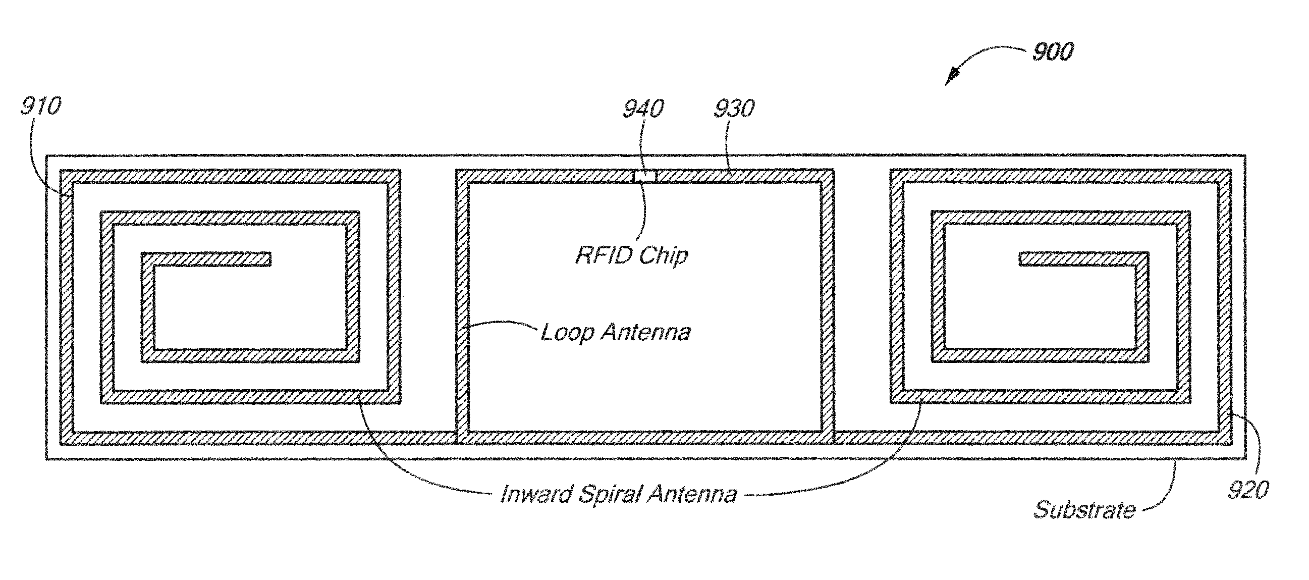
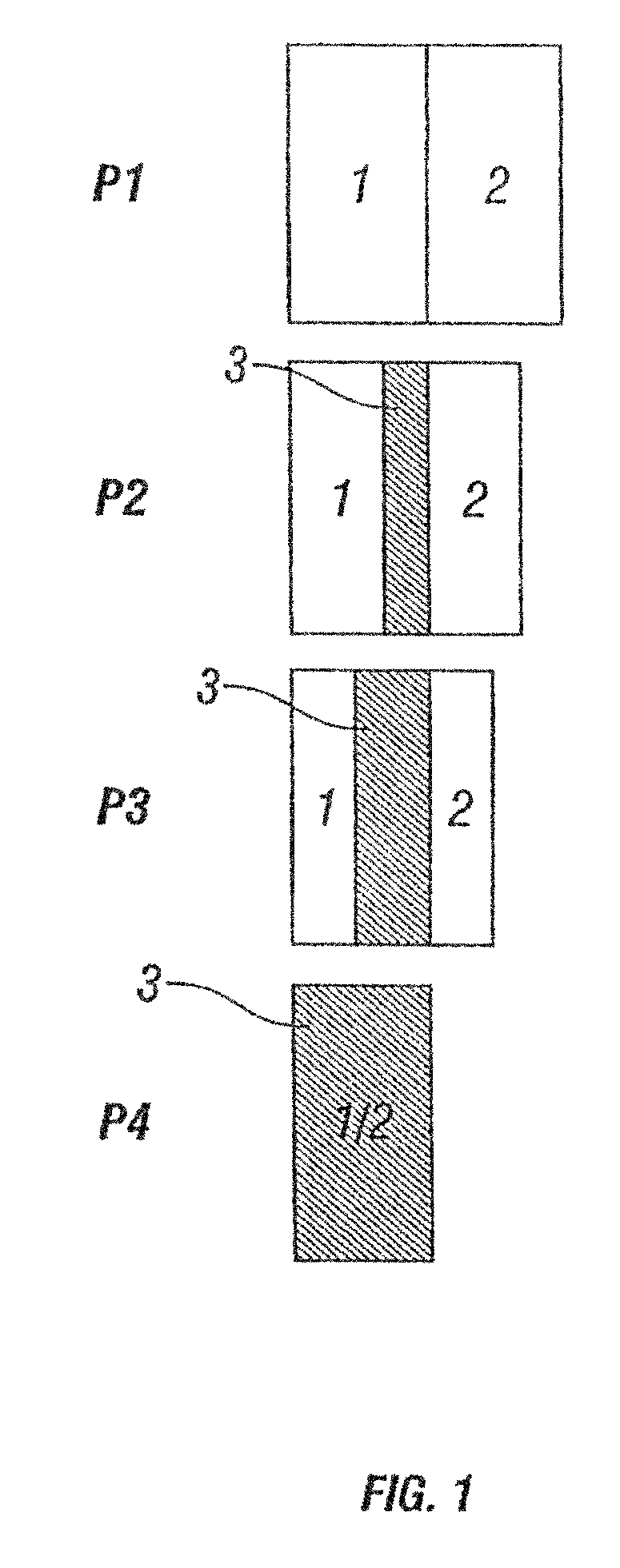
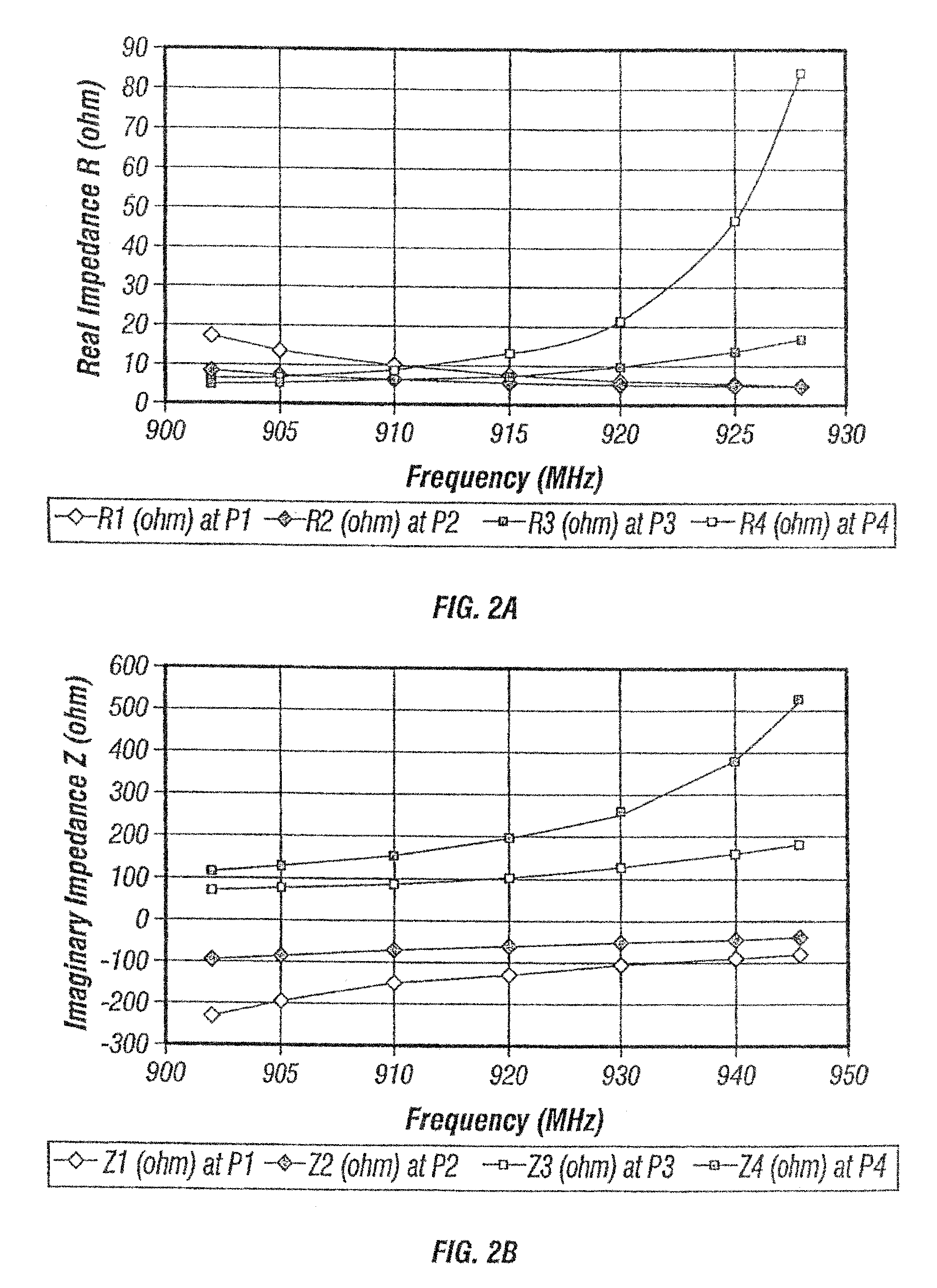
[0014]The present disclosure provides a security tag that includes an EAS component having a defined surface area, and an RFID component having a defined surface area. The EAS component surface area is configured to at least partially overlap the RFID component surface area. The RFID component includes an antenna which at least partially overlaps the first surface. A substantially planar spacer having a thickness is at least partially disposed between the defined surface areas of the EAS and RFID components. The RFID element read range is affected and controlled by the spacing between the RFID element and the EAS element. The RFID reader is capable of activating the RFID component when the RFID component is within the read range. The antenna includes a magnetic loop antenna coupled to a spiral antenna to increase near field read response.

Problems solved by technology

In addition, passing the article around the interrogation zone presents other problems because the EAS tag remains active and can interact with EAS systems in other controlled areas inadvertently activating those systems.
In some instances, the overall RFID read performance is optimized for the far field and the resulting near field read performance may be limited.
That is, the antenna cannot be optimized for both the far field and near field.
For combination EAS / RFID tag applications, a spiral antenna may limit the various options for near field antennas used in detachers and other POS applications where close proximity read performance is especially important.
The open antenna structure of a spiral antenna allows low frequency or static electric E field to develop a substantial voltage across the RFID chip and this can cause failure of the device if the level is high enough.
Retail stores already pay a considerable amount for hard tags that are re-useable.

Method used


Image

  • Combination EAS and RFID label or tag using a hybrid RFID antenna
  • Combination EAS and RFID label or tag using a hybrid RFID antenna
  • Combination EAS and RFID label or tag using a hybrid RFID antenna

Examples


Embodiment Construction

[0041]The present disclosure will be understood more fully from the detailed description given below and from the accompanying drawings of particular embodiments of the invention which, however, should not be taken to limit the invention to a specific embodiment but are for explanatory purposes.

[0042]Numerous specific details may be set forth herein to provide a thorough understanding of a number of possible embodiments of a combination EAS / RFID tag incorporating the present disclosure. It will be understood by those skilled in the art, however, that the embodiments may be practiced without these specific details. In other instances, well-known methods, procedures, components and circuits have not been described in detail so as not to obscure the embodiments. It can be appreciated that the specific structural and functional details disclosed herein may be representative and do not necessarily limit the scope of the embodiments.

[0043]Some embodiments may be described using the expres...


PUM


Abstract

A security tag includes an EAS component having a defined surface area, and an RFID component having a defined surface area. The EAS component surface area is configured to at least partially overlap the RFID component surface area. The RFID component includes an antenna which at least partially overlaps the first surface. A substantially planar spacer having a thickness is at least partially disposed between the defined surface areas of the EAS and RFID components. The RFID element read range is affected and controlled by the spacing between the RFID element and the EAS element. The RFID reader is capable of activating the RFID component when the RFID component is within the read range. The antenna includes a magnetic loop antenna in electrical contact with a spiral antenna to increase near field read response.

Description

CROSS-REFERENCE TO RELATED APPLICATION[0001]This application is a Continuation-in-Part Application of U.S. National Stage application Ser. No. 11 / 667,743, filed May 14, 2007, entitled COMBINATION EAS AND RFID LABEL OR TAG, based on PCT Application Number PCT / US2005 / 041573, filed Nov. 15, 2005, entitled COMBINATION EAS AND RFID LABEL OR TAG which is related to and claims priority to U.S. Provisional Application Ser. No. 60 / 628,303, filed Nov. 15, 2004, entitled COMBO EAS / RFID LABEL OR TAG, the entirety of which all are incorporated herein by reference.STATEMENT REGARDING FEDERALLY SPONSORED RESEARCH OR DEVELOPMENT[0002]n / aFIELD OF THE INVENTION[0003]The present disclosure relates to an electronic article surveillance (EAS) label or tag for the prevention or deterrence of unauthorized removal of articles from a controlled area. More particularly, the present disclosure relates to an EAS label or tag combined with a radiofrequency identification (RFID) label or tag for recordation of d...

Claims


Application Information

Patent Timeline
Patent Type & Authority Patents(United States)
IPC IPC(8): G08B13/14
CPCG06K19/0726G06K19/07749G08B13/2417G08B13/2431G08B13/2437G08B13/2448H01Q1/22H01Q1/2208H01Q1/2216H01Q1/2225H01Q1/38H01Q9/27H01Q9/285
Inventor COPELAND, RICHARD L.
Owner SENSORMATIC ELECTRONICS CORP
Why Eureka
Try Eureka