Composite shield structure of PMR writer for high track density

a composite shield and writer technology, applied in the field of composite shield structure, can solve the problems of complex structure, great challenge for wafer processing, and no prior art structure provides satisfactory control of field magnitude and field gradient in both directions

Inactive Publication Date: 2010-09-28
HEADWAY TECH INC
View PDF10 Cites 27 Cited by
  • Summary
  • Abstract
  • Description
  • Claims
  • Application Information

AI Technical Summary

Benefits of technology

[0011]One objective of the present invention is to provide a PMR writer structure that improves the cross-track field gradient while maintaining sufficient write field magnitude for applications including high recording density that have narrow track widths.
[0012]Another objective of the present invention is to provide a PMR writer structure according to the first objective that prevents adjacent track erasure and improves writability at narrow track width.
[0013]A still further objective of the present invention is to provide a PMR writer structure that can be more easily fabricated than a full side shield design.
[0016]From a top view, the main pole layer has a narrow write pole section containing the write pole tip at one end and a larger main pole layer section that flares outward from the end of the narrow write pole section that is opposite the pole tip. The main pole layer flare angle is from 45 degrees to 75 degrees to help the magnetic flux to concentrate at the pole tip and to counter balance the flux leakage loss to the partial side shield. Preferably, the partial side shields conform to the narrow write pole section and to a portion of the main pole layer adjacent to the narrow write pole section. In other words, each partial side shield has a first side that is parallel to the narrow write pole section of the main pole layer and a second side connected to the first side that is parallel to a flared side of the larger main pole layer section. A third side is formed along the ABS plane and a fourth side of the partial side shield may be perpendicular to the ABS plane and parallel to the first side.

Problems solved by technology

In addition, the complexity of the structure also poses a great challenge for wafer processing.
Unfortunately, none of the prior art structures provide satisfactory control of field magnitude and field gradient in both the down-track and cross-track directions.

Method used


Image

  • Composite shield structure of PMR writer for high track density
  • Composite shield structure of PMR writer for high track density
  • Composite shield structure of PMR writer for high track density

Examples


first embodiment

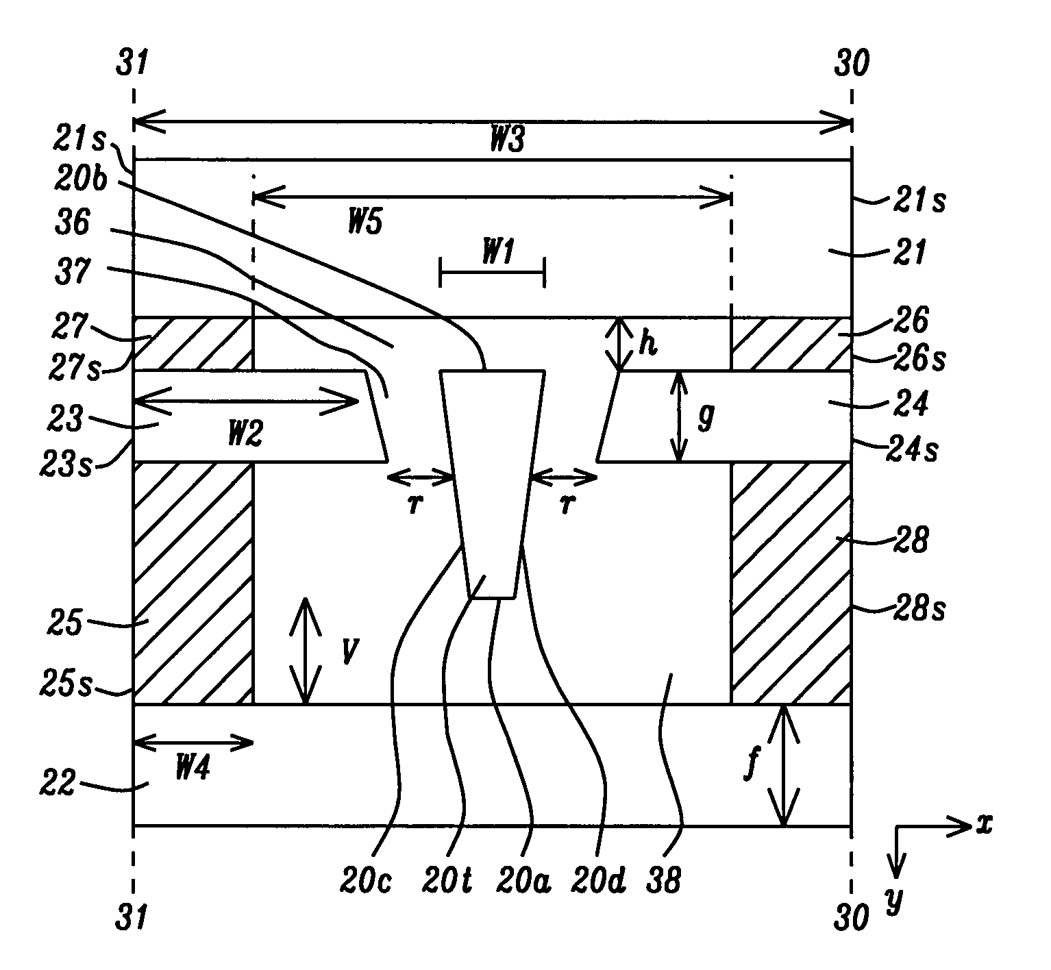
[0028]Referring to FIG. 6, a cross-sectional view is shown from an ABS plane that represents the present invention. There is a write pole having a surface (pole tip 20t) at the ABS comprised of a bottom edge 20a, a top edge 20b, and two sides 20c, 20d that is formed on a substrate (not shown) that may be a separation layer made of Al2O3 between a read head and a write head in a separated PMR read-write head, for example. However, the PMR writer is not limited to a separated PMR read-write head and may encompass other PMR writer configurations as appreciated by those skilled in the art. It should be understood that the write pole tip 20t has a bottom surface that terminates in the bottom edge 20a, and a top surface that terminates in the top edge 20b at the ABS. Furthermore, the substrate may be part of a slider (not shown) formed in an array of sliders on a wafer. After the PMR write head is completed, the wafer is sliced to form rows of sliders. Each row is typically lapped to affo...

second embodiment

[0036]Referring to FIG. 7, the composite shield structure according to the present invention is shown. The structure is the same as previously described with respect to FIG. 6 except that the side connections 26, 27 are omitted. In this case, side connections 25, 28 provide control of magnetic potential in partial side shield sections 23, 24 and in leading shield 22.

third embodiment

[0037]Referring to FIG. 8, the composite shield structure according to the present invention is shown. The structure is the same as previously described with respect to FIG. 6 except that the side connections 25, 28 are omitted. In this case, side connections 26, 27 provide magnetic potential control for partial side shields 23, 24 and trailing shield 21.

[0038]Referring to FIG. 9, a top view of the main pole layer 20, narrow section 20n, partial side shield sections 23, 24, and the larger section 20m of the main pole layer is illustrated. The trailing shield 21 above the pole tip 20t has been removed to simplify the drawing. The narrow section 20n extends from the pole tip 20t at the ABS plane to the plane 32-32 where the larger section 20m of the main pole layer flares outward at an angle θ with respect to the dashed lines 33, 34 that are extensions of the pole tip sides 20c, 20d, respectively. The angle θ is preferably between 45 degrees and 75 degrees to help concentrate the magn...


PUM

PropertyMeasurementUnit
distanceaaaaaaaaaa
distanceaaaaaaaaaa
thicknessaaaaaaaaaa

Abstract

Improved writability and a substantial reduction in adjacent track erasure are achieved by incorporating a composite shield structure in a PMR writer. There is a trailing shield formed a certain distance above the top surface of a write pole, a leading shield formed a certain distance below the bottom surface of the write pole, and a partial side shield having a section formed on each side of the write pole. The partial side shield thickness is less than that of the write pole. Each partial side shield section has a side that is parallel to the nearest write pole side and a top surface that is offset from the write pole top surface by 0 to 0.15 microns. A plurality of magnetic connections between two or more shield elements is employed to ensure correct magnetic potential. The large write pole has a flare angle of 45 to 75 degrees.

Description

RELATED PATENT APPLICATIONS[0001]This application is related to the following: Ser. No. 11 / 809,346, filing date May 31, 2007; and Ser. No. 11 / 787,015, filing date Apr. 13, 2007; both assigned to a common assignee.FIELD OF THE INVENTION[0002]The invention relates to a composite shield structure for a write pole in a perpendicular magnetic recording head in which a combination of trailing shield, partial side shield, and leading shield are employed to improve writability and prevent adjacent track erasure for narrow track widths.BACKGROUND OF THE INVENTION[0003]Perpendicular magnetic recording (PMR) has been developed in part to achieve higher recording density than is realized with longitudinal magnetic recording (LMR) devices and is believed to be the successor of LMR for next generation magnetic data storage products and beyond. A single pole writer combined with a soft magnetic underlayer has the intrinsic advantage of delivering higher write field than LMR heads. A conventional P...

Claims


Application Information

Patent Timeline
Patent Type & Authority Patents(United States)
IPC IPC(8): G11B5/127
CPCG11B5/11G11B5/1278G11B5/315G11B5/3146G11B5/3116
Inventor GUAN, LIJIEDOVEK, MORRISSMYTH, JOESASAKI, YOSHITAKA
Owner HEADWAY TECH INC
Why Eureka
Try Eureka