High resolution clock signal generator

Active Publication Date: 2010-09-28
CREDENCE SYSTEMS
View PDF17 Cites 4 Cited by
  • Summary
  • Abstract
  • Description
  • Claims
  • Application Information

AI Technical Summary

Benefits of technology

[0021]It is accordingly an object of the invention to provide a clock signal generator that can adjust a period of an output clock signal with high resolution.

Problems solved by technology

Thus both delay circuits are self-calibrating.

Method used


Image

  • High resolution clock signal generator
  • High resolution clock signal generator
  • High resolution clock signal generator

Examples


Embodiment Construction

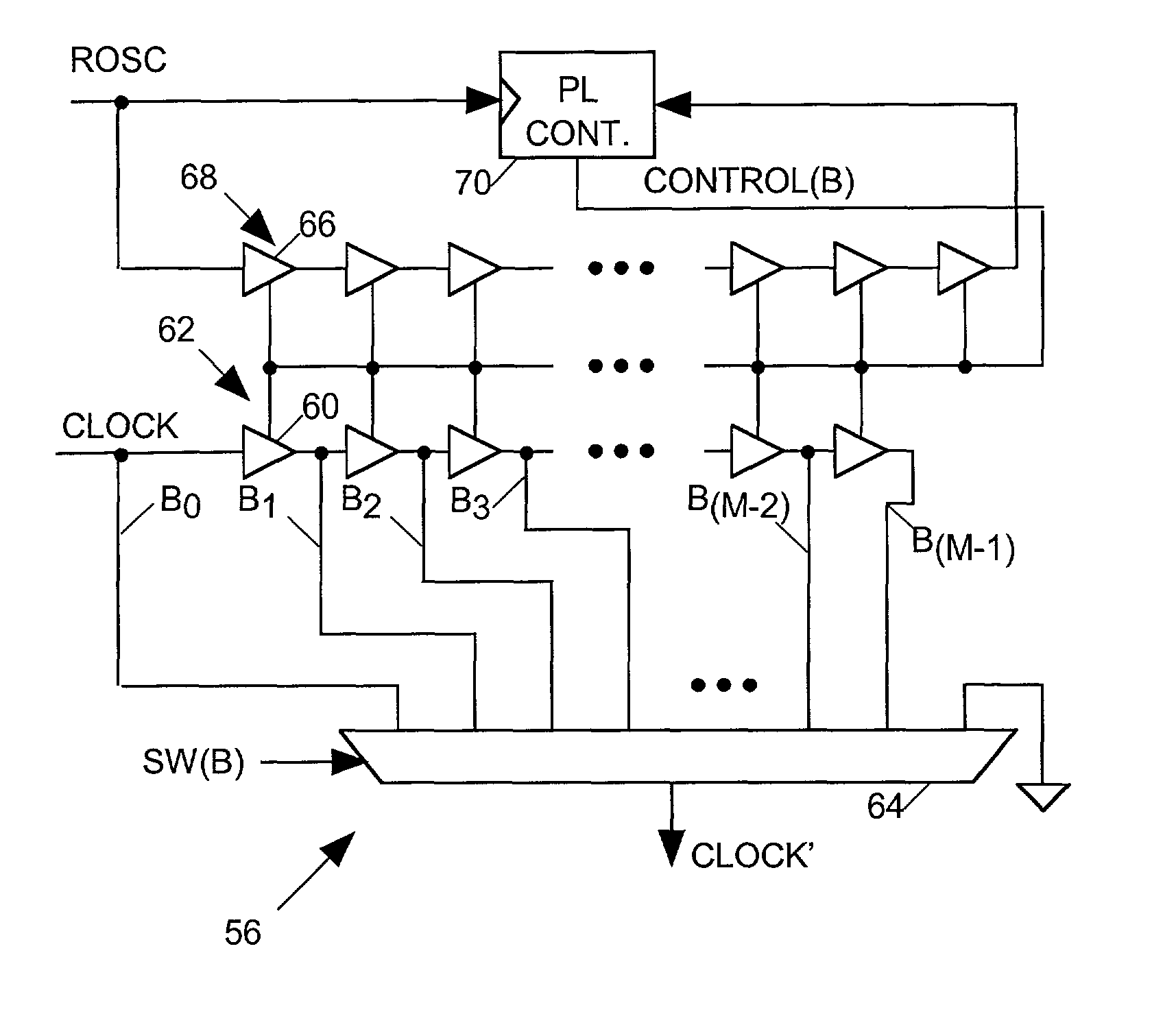
[0031]FIG. 5 depicts in block diagram form a high resolution programmable clock signal generator 50 in accordance with the invention for generating pulses of an output CLOCK′ signal by adjustably delaying pulses of a periodic reference signal ROSC having a period Tp through a pair of coarse delay circuits 54 and 56 connected in series. First coarse delay circuit 54 adjustably delays pulses of the ROSC signal over a range spanning at least Tp seconds with a resolution of Tp / N to provide output CLOCK signal pulses. The second coarse delay circuit 56 adjustably delays the CLOCK signal pulses over a range spanning Tp seconds with a resolution of Tp / M to provide pulses of the output CLOCK′ signal.

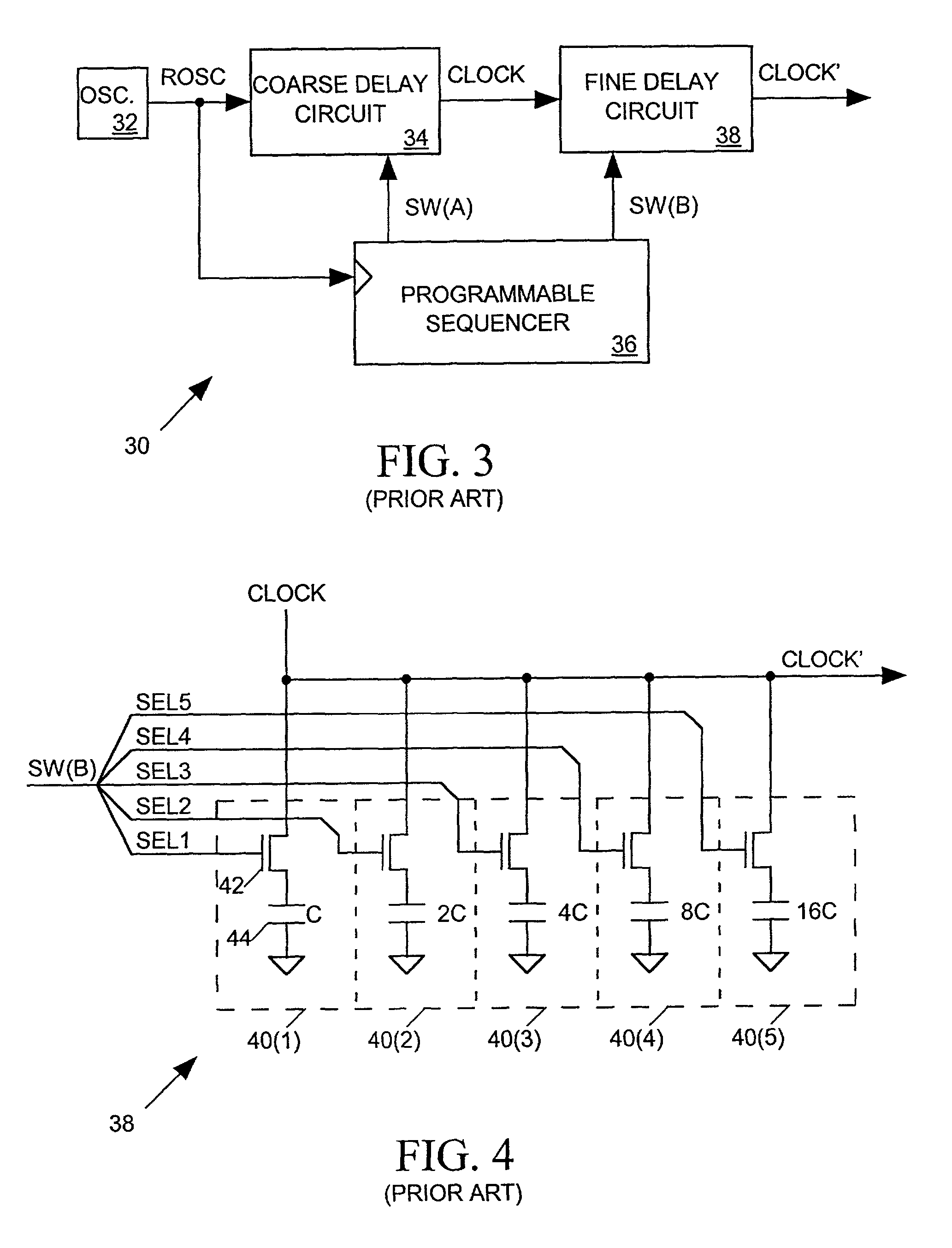
[0032]Although clock signal generator 50 and prior art clock signal generator 30 of FIG. 3 appear topologically somewhat similar, clock signal generator 30 employs one coarse delay circuit 34 and one fine delay circuit 38 whereas clock signal generator 50 employs two coarse delay circuits. A “co...


PUM


Abstract

A clock signal generator having first and second coarse delay circuits connected in series delays pulses of a reference signal having period Tp to produce pulses of the clock signal. The first coarse delay circuit delays pulses of the reference signal with a delay resolution of Tp / N seconds over a range spanning Tp seconds to produce pulses of an output signal. The second coarse delay circuit delays pulses of the output signal of the first coarse delay circuit over a range spanning Tp seconds with a delay resolution of TP / M seconds to provide pulses of the clock signal with a timing resolution of Tp / (M*N) seconds when the integers N and M are relatively prime.

Description

BACKGROUND OF THE INVENTION[0001]1. Field of the Invention[0002]The present invention relates in general to programmable clock signal generators and in particular to a high resolution programmable clock signal generator for providing a clock signal selected from a set of timing signals.[0003]2. Description of Related Art[0004]FIG. 1 depicts in block diagram form a prior art clock signal generator 10 for providing an adjustable frequency clock signal CLOCK synchronized to a reference clock signal ROSC provided by a stable oscillator 12. Clock signal generator 10 includes a set of N logic gates 14 connected in series to form a delay line 16 providing a set of N tap signals T0-TN-1 at the outputs of gates 14. Each gate 14 has a signal delay of TP / N so that each tap signal Tk is delayed with respect to the ROSC signal by an interval of PD=(k / N)*Tp, where Tp is the period of the ROSC signal.[0005]The ROSC signal and tap signal TN serve as inputs to a conventional phase lock (PL) controll...

Claims


Application Information

Patent Timeline
IPC IPC(8): G06F1/08H03K5/00H03K5/13H03K5/135H03L7/081
CPCH03K5/133H03K5/135H03L7/0805H03L7/0812H03K2005/00058H03K2005/00097
Inventor KUSHNICK, ERIC B.
Owner CREDENCE SYSTEMS
Why Eureka
Try Eureka