

Wiper blade
- Summary
- Abstract
- Description
- Claims
- Application Information
AI Technical Summary
Benefits of technology
Problems solved by technology
Method used
Image

Examples
Embodiment Construction
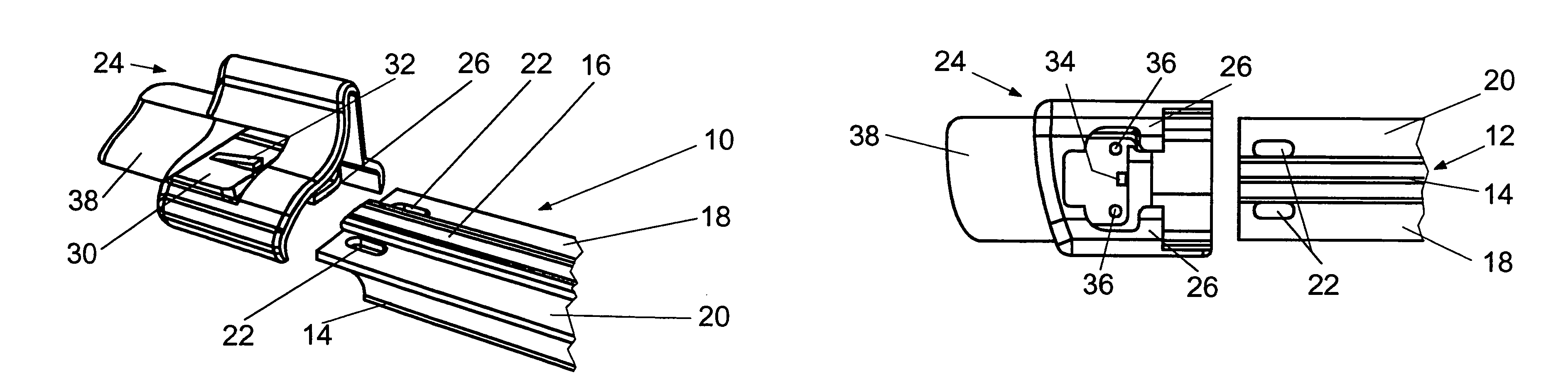
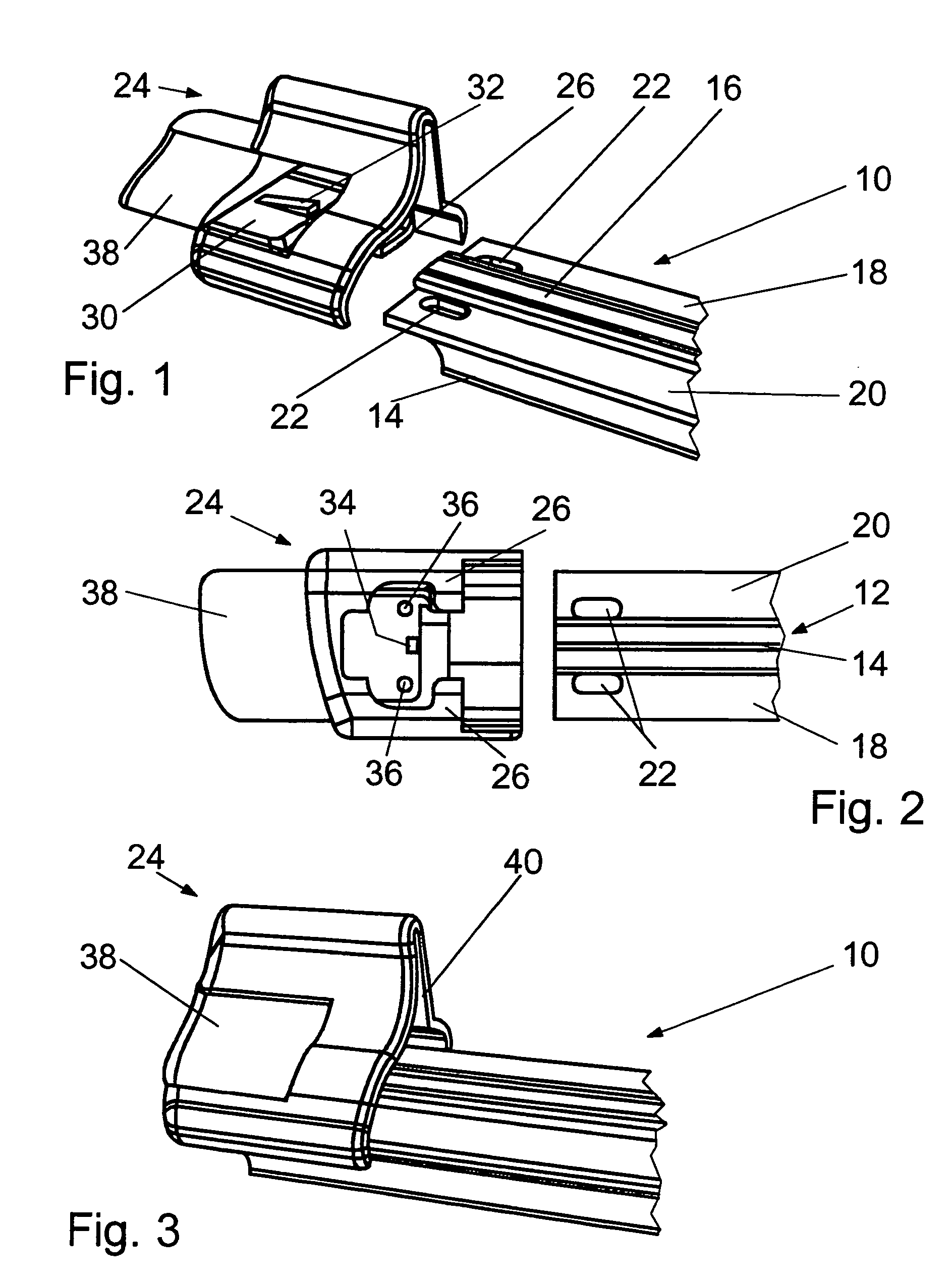
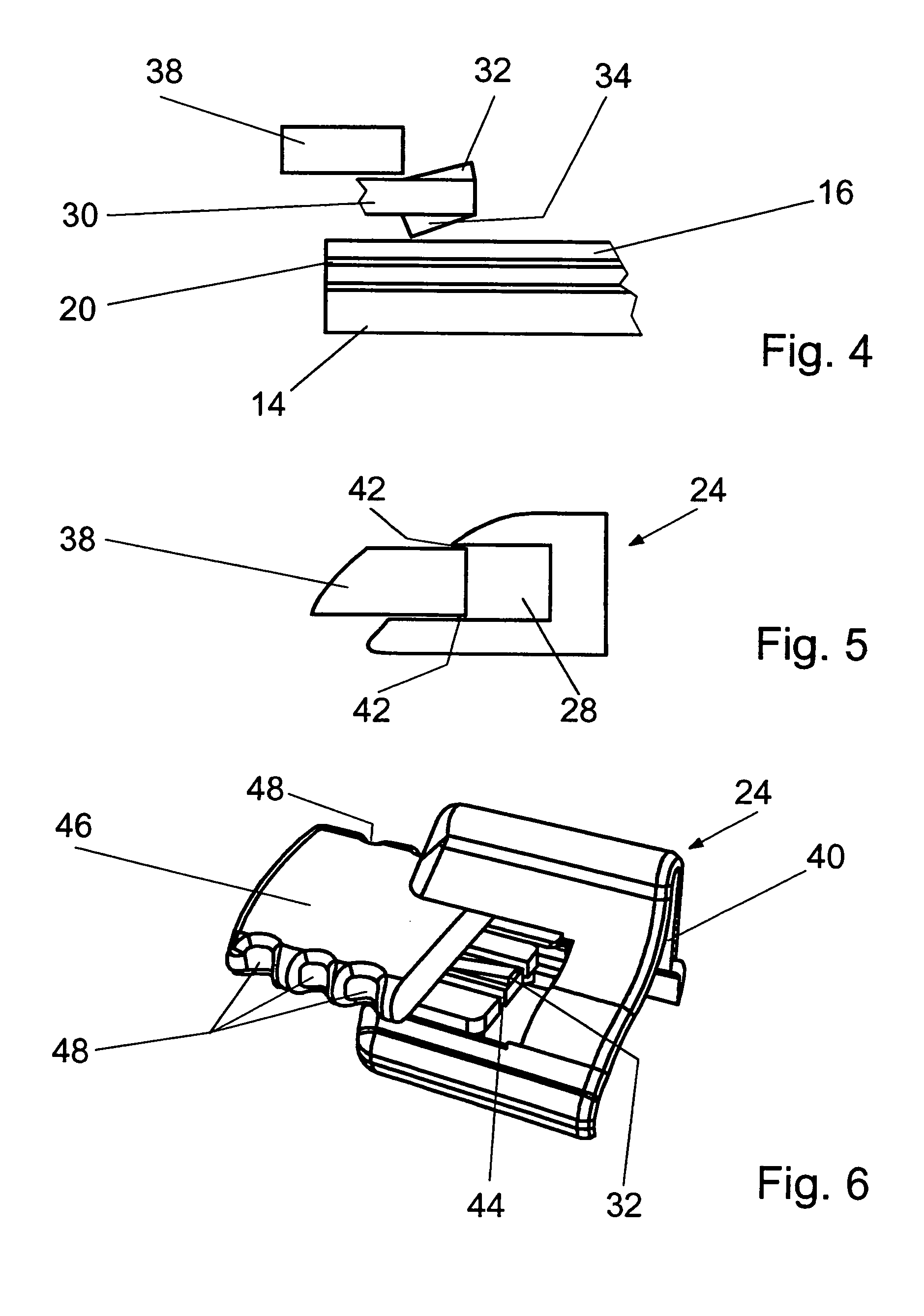
[0016]Only the parts of a non-articulated wiper blade 10 of a windshield wiper that are required to understand the invention are depicted (FIG. 1). The wiper blade 10 has a wiper strip 12 made of an elastomer material, whose lower side facing a windshield (not shown) is embodied as a wiper lip 14, while the upper side forms a top strip 16. In addition, the wiper blade 10 has a spoiler (not shown) above the top strip 16. In order to improve the spring characteristic of the wiper blade 10, it has two resilient rails 18 and 20 made of spring steel, which are inserted into lateral longitudinal grooves between the wiper lip 14 and the top strip 16 and serve as a support element. In an unstressed state, the resilient rails 18 and 20 have a greater curvature than the vehicle windshield and cause the wiper blade 10 to be adjacent to the vehicle windshield over the entire length under a defined application force and with a suitable distribution of pressure. The resilient rails 18 and 20 are ...
PUM
 Abstract
Description
Claims
Application Information