Ink-jet image forming apparatus and waste-ink processing method

a technology which is applied in the field of forming apparatus and waste-ink processing methods, can solve the problems of troublesome maintenance and difficult to facilitate cost reduction, and achieve the effects of improving the attractive feature of the product, facilitating the size reduction of the waste-ink tank, and improving the capacity of receiving the waste-ink

Active Publication Date: 2010-10-05
BROTHER KOGYO KK
View PDF5 Cites 0 Cited by
  • Summary
  • Abstract
  • Description
  • Claims
  • Application Information

AI Technical Summary

Benefits of technology

[0008]In view of this, in Japanese Patent Application Laid-open No. 2002-211007 (Pages 2 and 3, and FIGS. 1 to 4), an ink-jet image forming apparatus, in which a heating mechanism such as a heater for heating the waste-ink is provided to improve a waste-ink receiving capacity of the waste-ink tank by enhancing drying, has been proposed. Accordingly, it is possible to reduce a size of the waste-ink tank.
[0038]According to the waste-ink processing method of the present invention, evaporation of the waste-ink stored in the waste-ink tank is expedited, and it is possible to facilitate a size reduction of the waste-ink tank. Therefore, it is possible to improve a capacity of receiving the waste-ink of the waste-ink tank, and to improve the attractive feature of the product by reducing the size of the waste-ink tank, and making the designing and the design easy.

Problems solved by technology

Therefore, the waste-ink tank occupies a large space inside the product, and imparts a substantial constraint on a design etc.
When the ink absorbing material is let to be replaceable, and changed appropriately, it is possible to use a small ink absorbing material, but it is necessary to change the ink absorbing material frequently, and the maintenance becomes a troublesome task.
Further, from a cost point of view, in the former, large-size ink absorbing material hinders a cost reduction, and the latter, even though small, since a large number of ink absorbing materials are necessary, it is difficult to facilitate the cost reduction.

Method used


Image

  • Ink-jet image forming apparatus and waste-ink processing method
  • Ink-jet image forming apparatus and waste-ink processing method
  • Ink-jet image forming apparatus and waste-ink processing method

Examples


Embodiment Construction

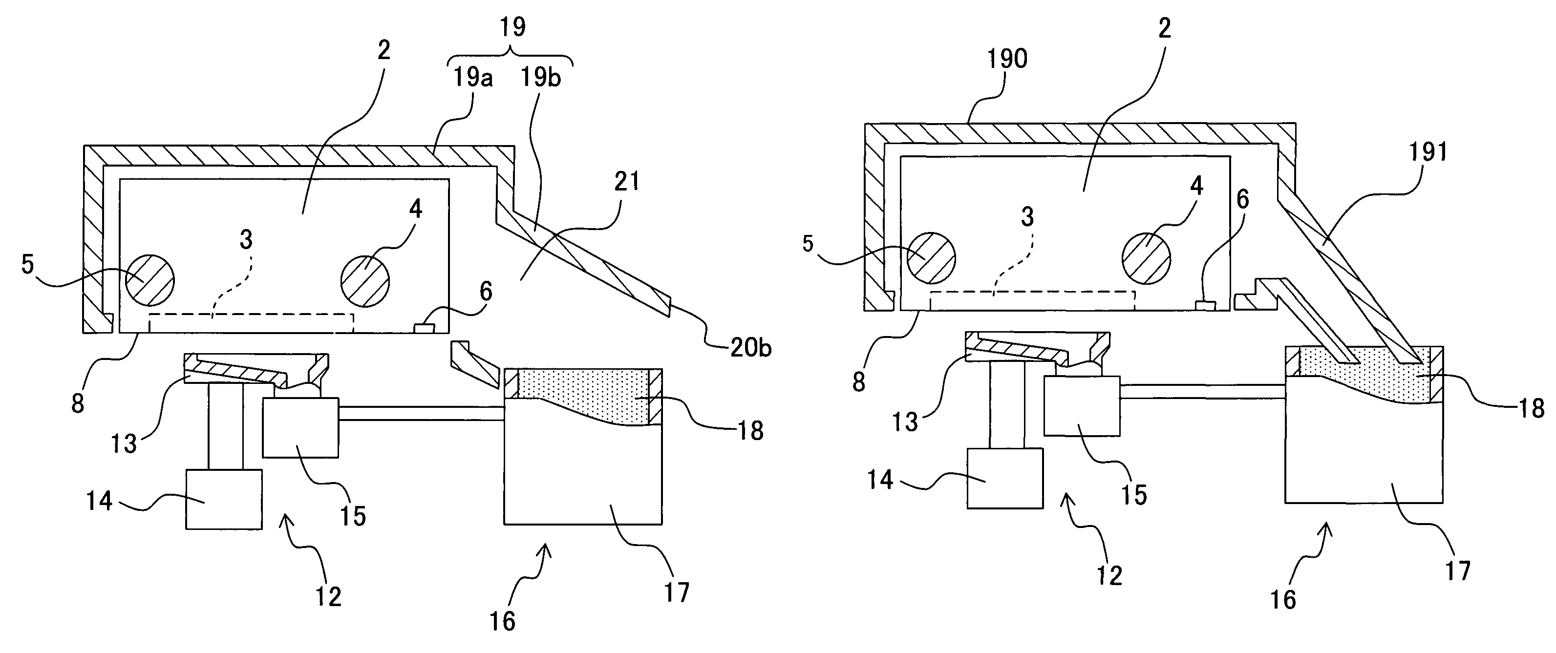
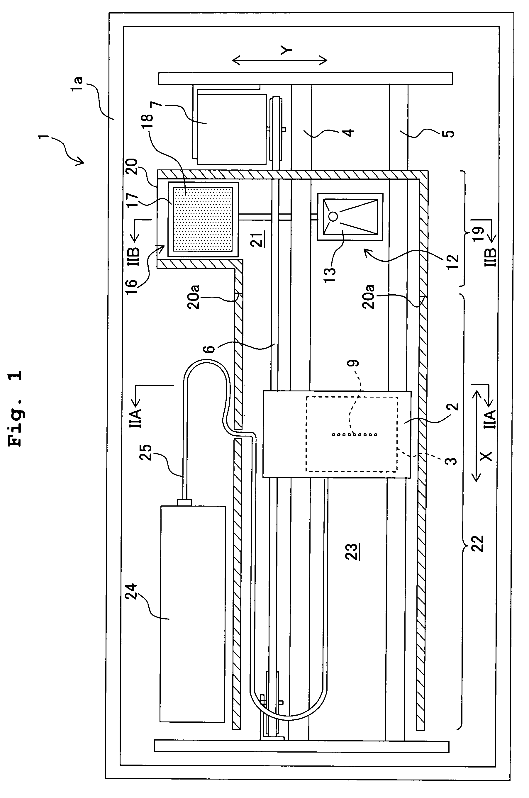
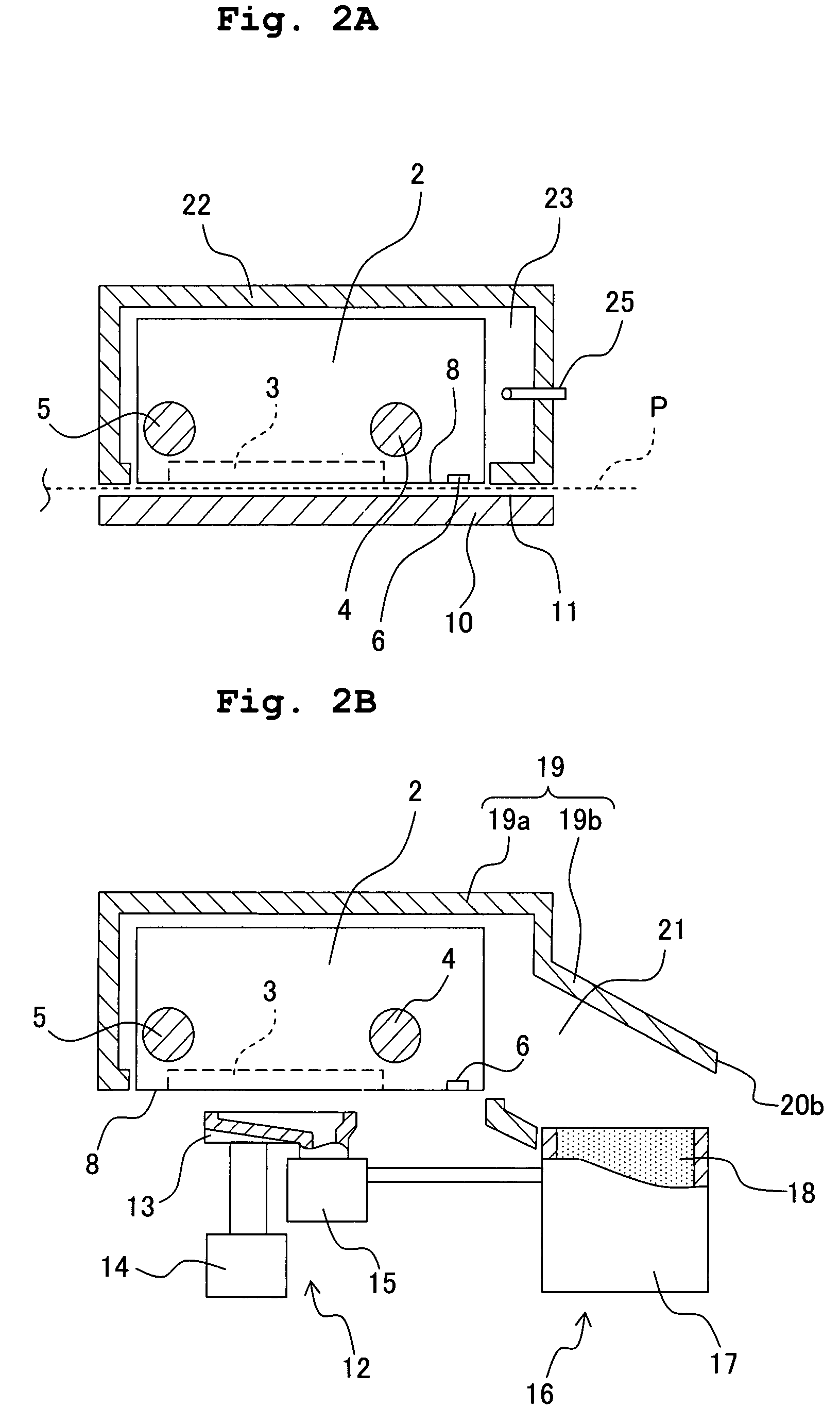
[0045]An embodiment of an ink-jet image forming apparatus of the present invention will be described below with reference to the accompanying diagrams. FIG. 1 shows a schematic plan view of an ink-jet image forming apparatus 1, and FIGS. 2A and 2B show a cross-sectional view taken along a line IIA-IIA in FIG. 1, and a cross-sectional view taken along a line IIB-IIB in FIG. 1 respectively.

[0046]As shown in FIG. 1, the ink-jet image forming apparatus (ink-jet printer) 1 includes mainly a body cover 1A, a carriage 2, a recording head 3, a pair of guide members 4 and 5, an endless belt 6, a drive unit 7, a maintenance unit 12, and a waste-ink tank 16. The carriage 2 also functions as a head holder on which the recording head 3 is mounted, and which reciprocates in a main scanning direction shown by an arrow X in the diagram. The carriage 2 is provided to bridge the pair of guide members 4 and 5 arranged to be isolated in a secondary scanning direction (Y direction in FIG. 1). The carria...


PUM


Abstract

An ink-jet image forming apparatus includes a recording head in which a plurality of nozzle groups jetting an ink is formed, a carriage which is mounted on the recording head, and which is capable of reciprocating in a predetermined direction, a waste-ink tank which stores the ink discharged from a the nozzle groups, and an air guide section which expedites evaporation of waste-ink by guiding a flow of air generated by the carriage movement to the waste-ink tank. Accordingly, it is possible to make the waste-ink tank compact without reducing an amount to be received of the waste-ink.

Description

CROSS REFERENCE TO RELATED APPLICATION[0001]The present application claims priority from Japanese Patent Application No. 2006-138775 filed on May 18, 2006, the disclosure of which is incorporated herein by reference in its entirety.BACKGROUND OF THE INVENTION[0002]1. Field of the Invention[0003]The present invention relates to an ink-jet image forming apparatus which adheres ink droplets to a surface of a recording medium by jetting the ink droplets on to the recording medium, and records characters and diagrams and the like, and a waste-ink processing method (waste-ink disposal method).[0004]2. Description of the Related Art[0005]An ink-jet image forming apparatus expresses characters and diagrams and the like by jetting droplets of an ink toward a recording medium such as a plain paper, and forming a plurality of dots by adhering the droplets of ink on the recording paper. The droplets of ink are jetted on to the recording medium at a high speed from a plurality of fine nozzles fo...

Claims


Application Information

Patent Timeline
Patent Type & Authority Patents(United States)
IPC IPC(8): B41J2/165
CPCB41J2/1721B41J2002/1742
Inventor SAKURAI, HISAKI
Owner BROTHER KOGYO KK
Why Eureka
Try Eureka