Wireless communication device

a communication device and wireless technology, applied in the field of wireless communication devices, can solve the problems of increasing data rate requirements, increasing transmission power, and increasing antenna size in view of the size of the wireless portable device, so as to increase the reception capacity, reduce losses, and increase the signal to noise and interference ratio

Inactive Publication Date: 2013-11-21
TELEFON AB LM ERICSSON (PUBL)
View PDF2 Cites 1 Cited by
  • Summary
  • Abstract
  • Description
  • Claims
  • Application Information

AI Technical Summary

Benefits of technology

[0006]The object is according to an aspect of the invention achieved by a wireless communication device having an upper part and a bottom part. The upper part comprises one or more transmission antenna device(s). The upper part and the bottom part are arranged movably in relation to each other, so that the bottom part, in use mode, is closer to the user than the upper part, and the bottom part comprises one or more reception antenna device(s). By placing reception antenna devices in the part closest to the user when using the portable wireless communication device, an increased reception capacity is provided without entailing any requirements for performing SAR measurements. Further, the placement of the reception antenna device(s) in the bottom part enables the reduction of losses as required cables between reception antennas and radio circuitry can be shortened, thereby increasing the received signal to noise and interference ratio.
[0007]In an embodiment of the invention, the upper part further comprises one or more reception antenna device. This is the case for many wireless communication devices, and the provision of additional reception antenna devices in the bottom part provides an increased reception capacity to such wireless communication devices.
[0008]In a variation of the above embodiment, the bottom part comprises one or more reception antenna devices arranged to receive a polarization orthogonal to the polarization of the one or more reception antenna devices of the upper part. An improved reception is provided in that an additional polarization direction can be used therefore.

Problems solved by technology

However, increased data rates put requirements on e.g. the antennas used.
An increase in antenna size is difficult in view of the size of the wireless portable device, and an increase in transmission power is difficult for a number of reasons.
Otherwise, such SAR measurements need to be performed for every antenna implementation, which would be very costly and also time-consuming for the manufacturers.

Method used


Image

  • Wireless communication device
  • Wireless communication device

Examples


Embodiment Construction

[0018]In the following description, for purposes of explanation and not limitation, specific details are set forth such as particular architectures, interfaces, techniques, etc. in order to provide a thorough understanding of the invention. However, it will be apparent to those skilled in the art that the invention may be practiced in other embodiments that depart from these specific details. In other instances, detailed descriptions of well-known devices, circuits, and methods are omitted so as not to obscure the description of the invention with unnecessary detail. Like numbers refer to like elements throughout the description.

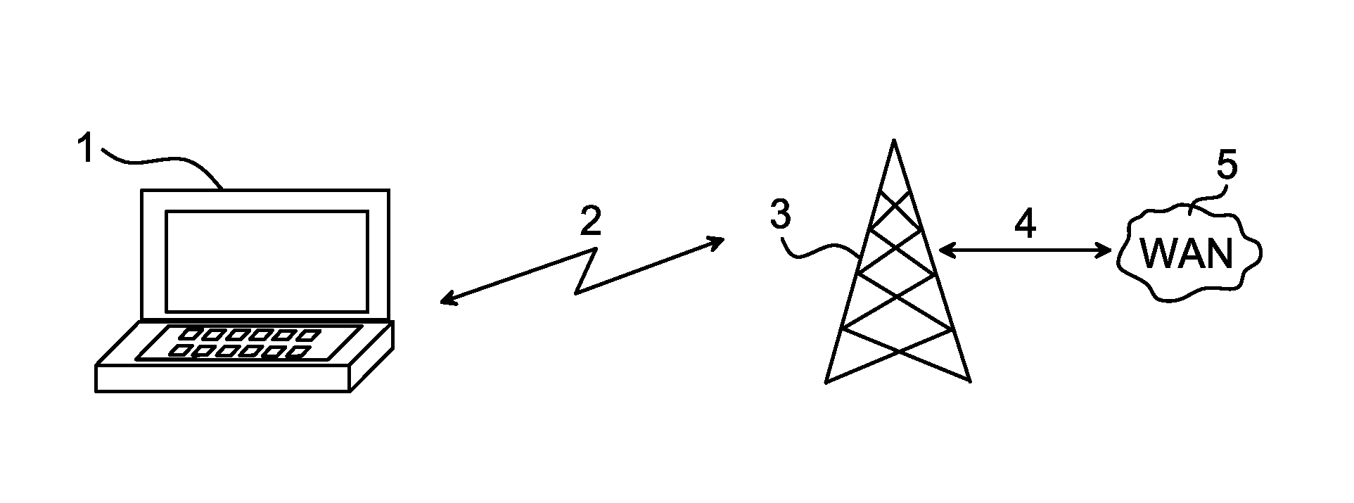
[0019]FIG. 1 illustrates an exemplary environment in which an embodiment of the invention may be implemented. A wireless communication device 1 is able to communicate with other devices and comprises for this end data exchanging means able to receive and transmit data. The communication is performed over a wireless communication link, schematically illustrat...


PUM


Abstract

The invention relates to a wireless communication device having an upper part 10 and a bottom part 11, the upper part 0 comprising one or more transmission antenna device(s) 12a, 12b; 15. The upper part 10 and the bottom part 11 are arranged movably in relation to each other, so that the bottom part 11, in use mode, is closer to the user than the upper part 10. The bottom part 11 comprises one or more reception antenna device(s) 14a, 14b, 14c, 14d.

Description

FIELD OF THE INVENTION[0001]The invention relates to wireless communication devices, and in particular to wireless communication devices having an upper part and a bottom part arranged movably in relation to each other.BACKGROUND OF THE INVENTION[0002]Wireless communication devices, such as mobile phones and laptops, are an expected part of everyday life, and an increasing number of services are offered to users of these wireless communication devices. Examples of such services comprise video on demand, e-mail, downloading of music and surfing the Internet, just to mention a few. The provided services become increasingly more bandwidth requiring and the number of users is also increasing. Further, higher data rates for the services are a desire of both users as well as of the service providers, enabling a rapid exchange of data.[0003]In view of e.g. the vast number of services being offered, the need and demand for increased data rates and bandwidth is most understandable. However, ...

Claims


Application Information

Patent Timeline
Patent Type & Authority Applications(United States)
IPC IPC(8): H04B1/38
CPCH04B1/38G06F1/1698H04B1/3838
Inventor NILSSON, ANDREASDERNERYO, ANDERSSTJERNMAN, ANDERS
Owner TELEFON AB LM ERICSSON (PUBL)
Why Eureka
Try Eureka