LED illumination assembly with compliant foil construction

a technology of led illumination and foil construction, which is applied in the direction of lighting and heating apparatus, semiconductor devices for light sources, and support devices for lighting and heating. it can solve the problems of reducing the life of leds, increasing local temperatures around led dies, and unable to quickly transport the heat generated in leds away from leds. it can improve the thermal conductivity of the insulating layer

Inactive Publication Date: 2010-10-05
3M INNOVATIVE PROPERTIES CO
View PDF17 Cites 19 Cited by
  • Summary
  • Abstract
  • Description
  • Claims
  • Application Information

AI Technical Summary

Problems solved by technology

However, tightly packing large numbers of LEDs in an array is a long term reliability concern since local heating, even with a globally efficient thermal conduction mechanism, can reduce the lifespan of the LEDs.
In other applications, even those without high packing densities, the driving voltages / currents and brightness of LED dies are increasing, leading to increases in local temperatures around the LED dies.
), that are unable to quickly transport the heat generated in the LED away from the LED.
As a consequence, performance of the device is limited.
Applicants of the present application have found that, although the more recent approaches improve the thermal properties of LED arrays, there are disadvantages to these approaches.
Specifically, the substrates on which the LED arrays are disposed have limited ability to form local features having sizes useful for fully using, controlling, and manipulating the light emitted from the LEDs.

Method used


Image

  • LED illumination assembly with compliant foil construction
  • LED illumination assembly with compliant foil construction
  • LED illumination assembly with compliant foil construction

Examples


Embodiment Construction

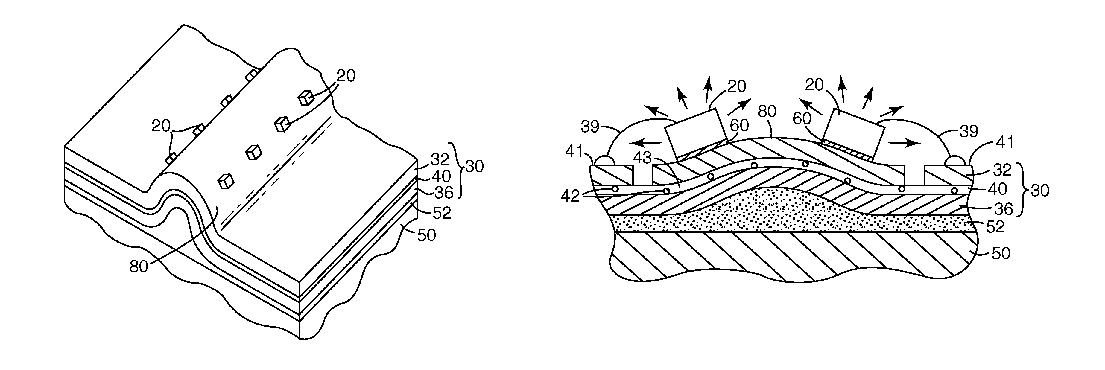
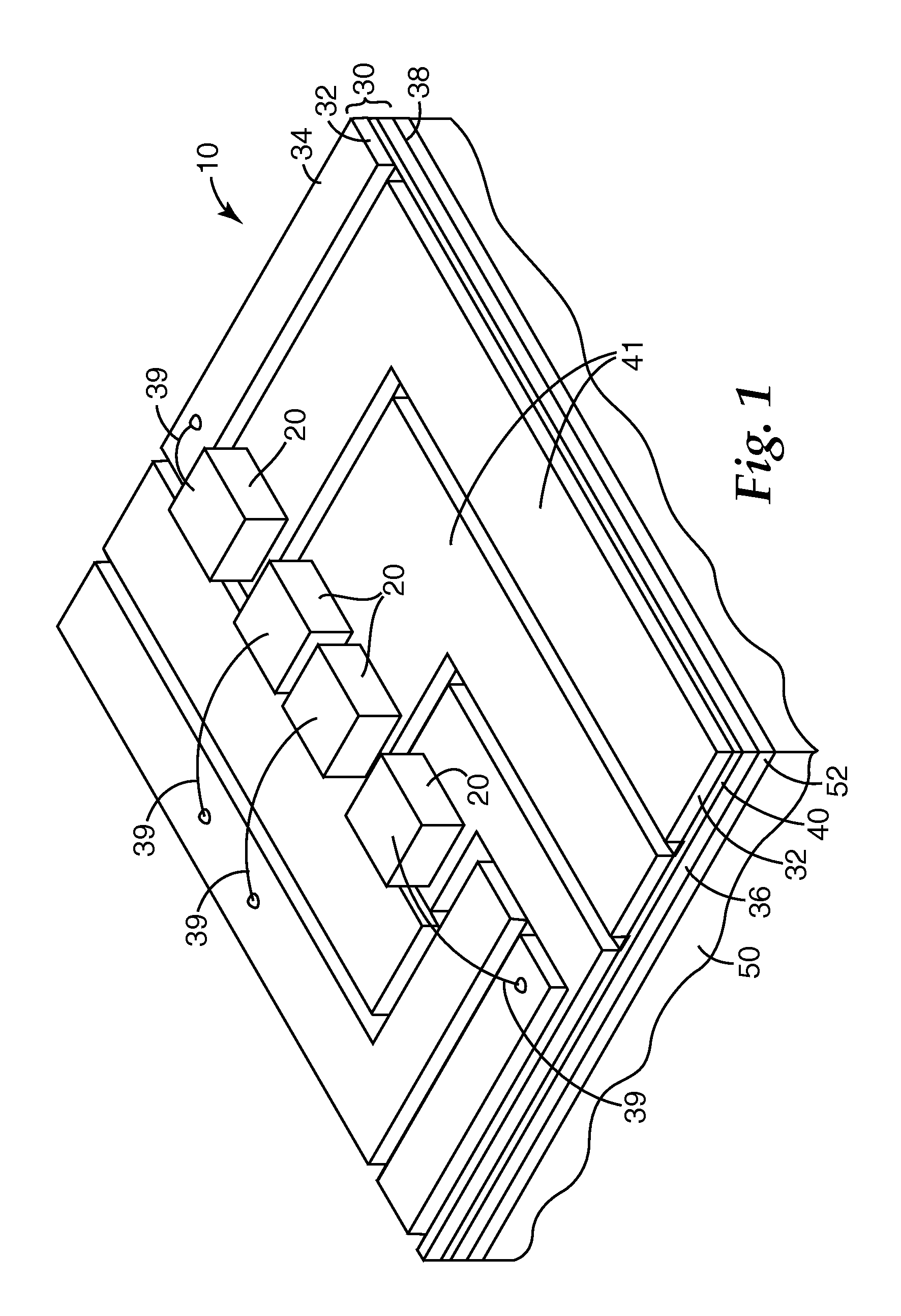
[0023]We describe herein illumination assemblies that include LED dies. In this regard, “light emitting diode” or “LED” refers to a diode that emits light, whether visible, ultraviolet, or infrared. It includes incoherent encased or encapsulated semiconductor devices marketed as “LEDs”, whether of the conventional or super radiant variety. If the LED emits non-visible light such as ultraviolet light, and in some cases where it emits visible light, it can be packaged to include an organic or inorganic phosphor (or it may illuminate a remotely disposed phosphor) to convert short wavelength light to longer wavelength visible light, in some cases yielding a device that emits white light. An “LED die” is an LED in its most basic form, i.e., in the form of an individual component or chip made by semiconductor processing procedures. For example, the LED die is ordinarily formed from a combination of one or more Group III elements and of one or more Group V elements (III-V semiconductor). E...


PUM


Abstract

An illumination assembly includes a compliant substrate comprising a first and second electrically conductive foil separated by an electrically insulating layer. The insulating layer includes a polymer material loaded with particles that enhance thermal conductivity of the insulating layer. A plurality of LED dies are disposed on the first conductive foil.

Description

CROSS REFERENCE TO RELATED APPLICATIONS[0001]This application is a divisional of U.S. Ser. No. 11 / 669,622, filed Jan. 31, 2007, now U.S. Pat. No. 7,572,031, the disclosure of which is incorporated by reference in its entirety herein.FIELD OF THE INVENTION[0002]The present invention relates to light emitting diode (LED) devices, liquid crystal display (LCD) devices, components therefor, and related articles and processes.BACKGROUND[0003]LEDs are a desirable choice of light source in part because of their relatively small size, low power / current requirements, rapid response time, long life, robust packaging, variety of available output wavelengths, and compatibility with modern circuit construction. These characteristics may help explain their widespread use over the past few decades in a multitude of different end use applications. Improvements to LEDs continue to be made in the areas of efficiency, brightness, and output wavelength, further enlarging the scope of potential end-use a...

Claims


Application Information

Patent Timeline
Patent Type & Authority Patents(United States)
IPC IPC(8): F21V33/00
CPCH05K1/0203H05K1/189F21K9/00H05K1/0373H05K3/0061H05K3/386H05K2201/0209H05K2201/091H05K2201/09363H05K2201/10106H01L2224/48091H01L2224/48471H01L2224/73265Y10S362/80H01L2924/00014H01L2924/3011H01L2924/00H01L2224/4554
Inventor SCHULTZ, JOHN C.OUDERKIRK, ANDREW J.PEIFFER, JOEL S.O'BRYAN, NELSON B.WHEATLEY, JOHN A.MURRAY, CAMERON T.
Owner 3M INNOVATIVE PROPERTIES CO
Why Eureka
Try Eureka