Pitching machine

a technology of pitching machine and projector, which is applied in the direction of compressed gas gun, white arms/cold weapons, weapons, etc., can solve the problems of batter's inability to coordinate the beginning of the swing with the motion of the arm, the machine is unsatisfactory, and the batter's timing is not improved, so as to achieve the effect of low weight and inexpensive manufacturing

Inactive Publication Date: 2010-10-05
NEUMAN DANIEL R
View PDF98 Cites 34 Cited by
  • Summary
  • Abstract
  • Description
  • Claims
  • Application Information

AI Technical Summary

Benefits of technology

[0011]The general object of this invention is to provide an improved windmill pitching machine. A particular object is to provide a windmill pitching machine that closely simulates the pitching motion of a human pitcher and is also relatively light in weight and inexpensive.
[0013]The pitching machine of this invention simulates the pitching motion of a human pitcher because of its rotating pitching arm. It further simulates the snap of the wrist because of the rotating wheel provides additional velocity. The pitching machine is relatively light in weight and inexpensive to manufacture.

Problems solved by technology

These machines are unsatisfactory because they do not simulate the motion of an actual pitcher.
In particular, the batter's sense of timing is not improved because he or she cannot coordinate the beginning of the swing with the motion of an arm.
As a result, the batter cannot coordinate the beginning of the swing with the motion of the arm.
Because these machines rely solely upon the speed attained by the arm during this arc to provide velocity to the pitched ball, the batter cannot coordinate the beginning of the swing with the motion of the arm.
The only disadvantage of the Neuman pitching machine is that the pitching arm strikes a stop member with so much force that the machine must be very sturdy.
Accordingly, the Neuman pitching machine is relatively heavy and expensive.

Method used


Image

  • Pitching machine
  • Pitching machine
  • Pitching machine

Examples


Embodiment Construction

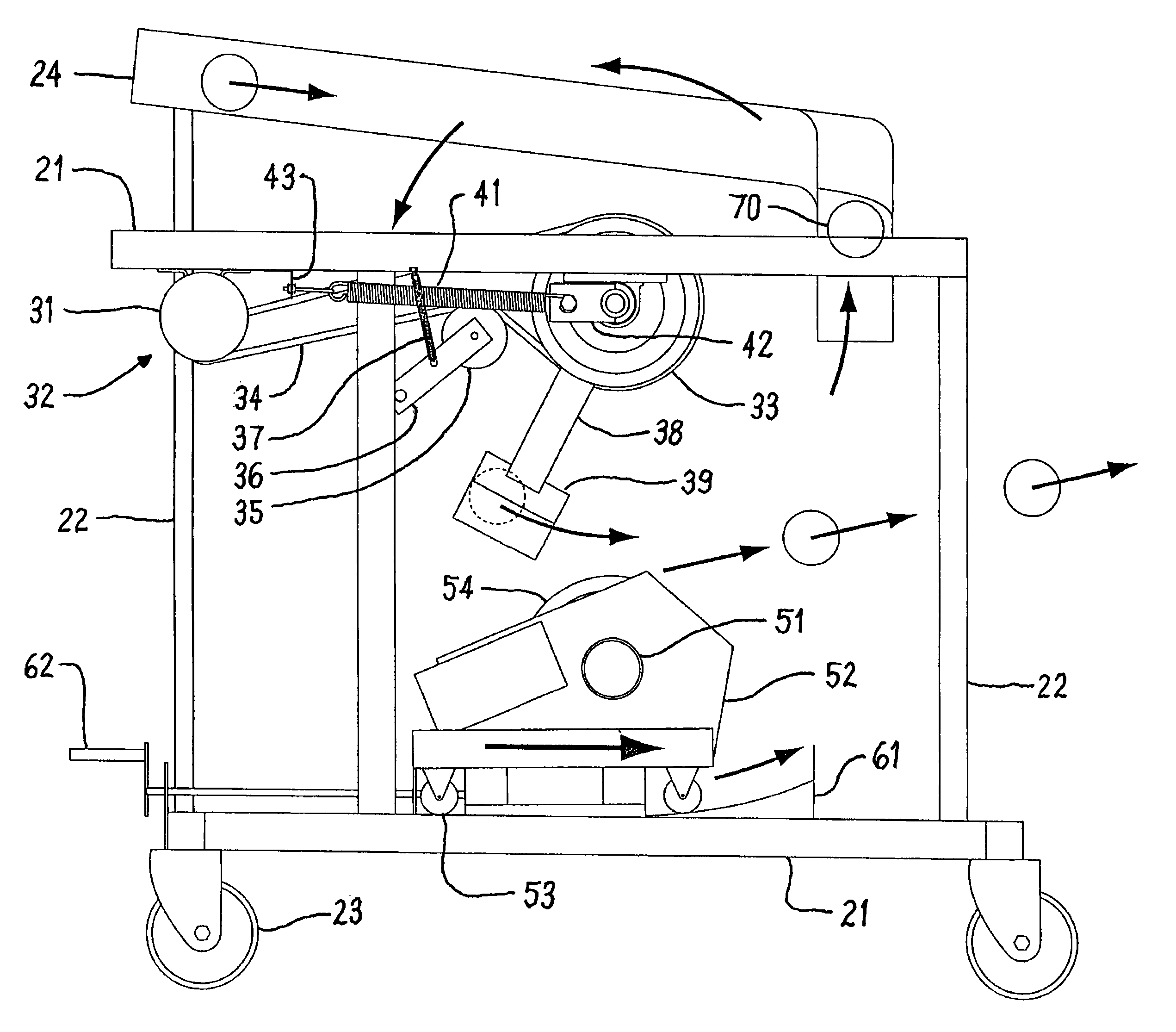
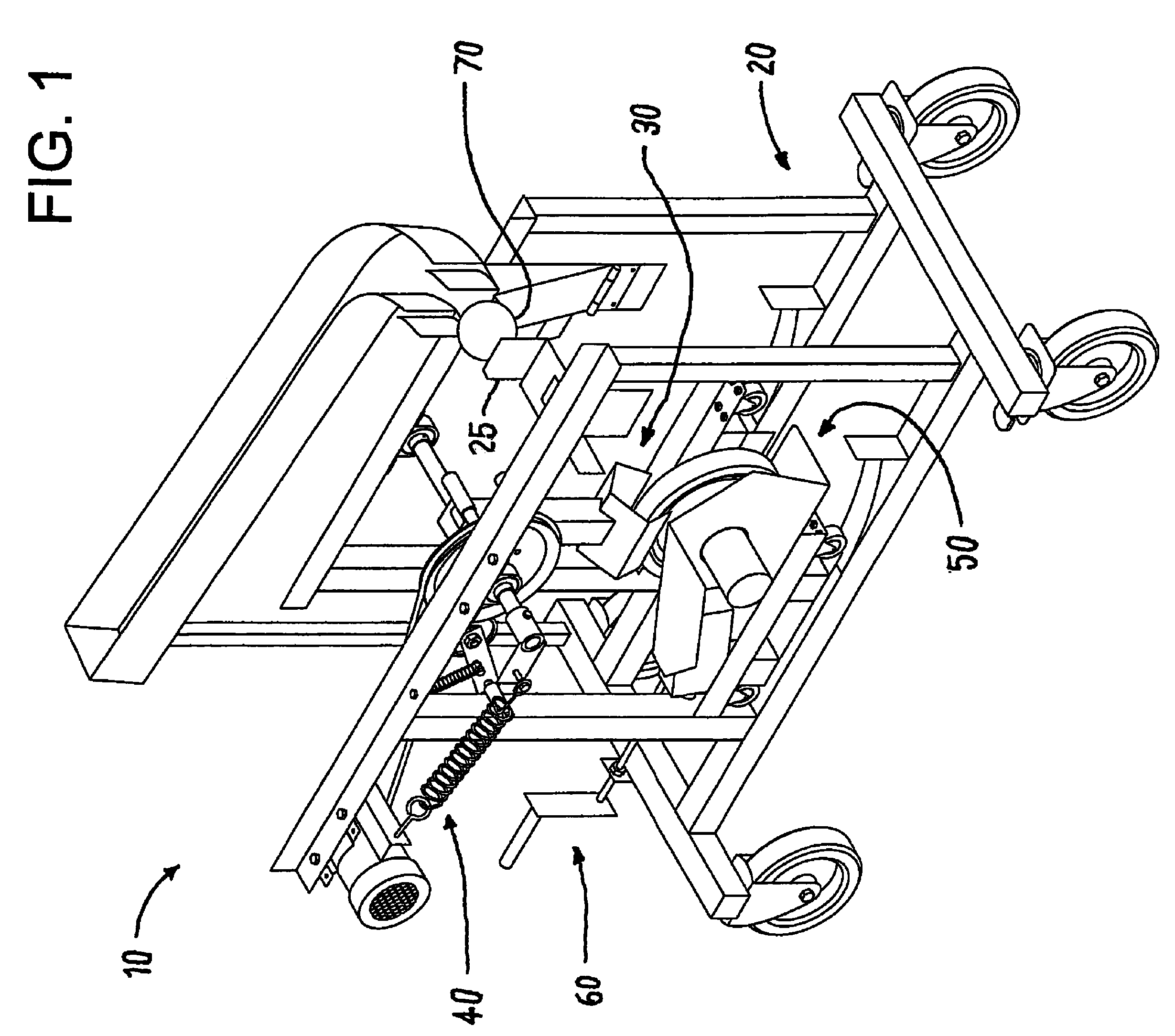
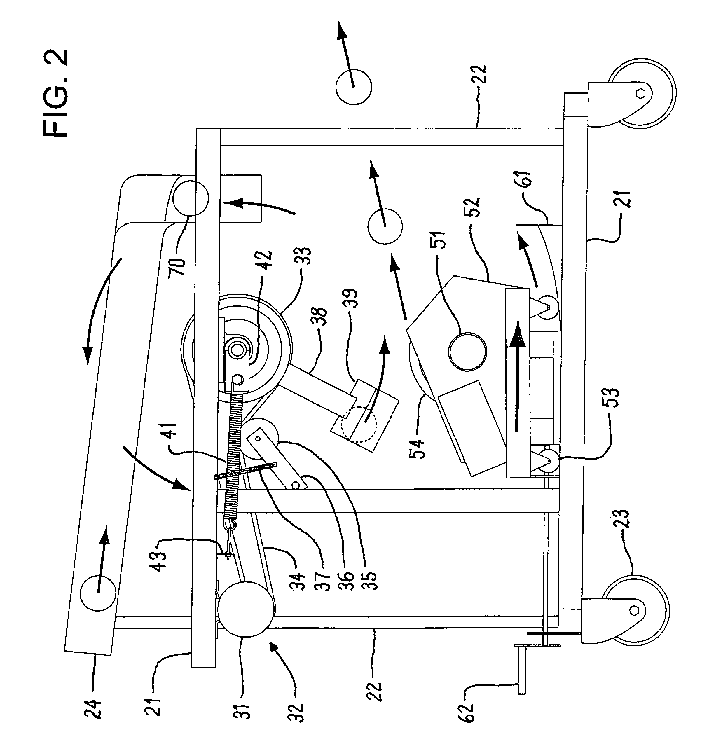
[0023]This invention is best understood by reference to the drawings. Referring first to FIGS. 1 and 2, the pitching machine 10 of this invention comprises a frame 20, a windmill pitching arm assembly 30 including an optional pitching arm acceleration assembly 40, and a pitching wheel assembly 50 including an optional launch angle adjustment assembly 60. Each of these components is discussed in detail below.

[0024]1. Frame

[0025]The frame 20 provides the overall structure of the pitching machine and the other components are attached to it. The frame includes upper and lower horizontal members 21 and front and rear vertical members 22. If it is desired to move the pitching machine from place to place, the frame sits on wheels 23. If the frame sits on wheels, it may be desirable to include brakes, stands, wheel chocks, or the like (not shown) to prevent any movement while the pitching machine is in operation.

[0026]The frame contains a ball magazine 24 consisting of an inclined ramp that...


PUM


Abstract

A pitching machine contains a pitching arm that vertically rotates at a speed of about 5 to 15 rpm, picks up a ball from the ball cradle at a pick-up point in its rotation, and then releases the ball at a release point in its rotation to provide a first velocity component to the ball. The pitching machine also contains a wheel that vertically rotates at a speed of about 300 to 3000 rpm. The wheel is positioned at the release point of the pitching arm to provide a second velocity component to the ball and to pitch the ball at an initial launch angle.

Description

CROSS-REFERENCE TO RELATED APPLICATION[0001]This application claims the benefit of U.S. Provisional Application Ser. No. 60 / 933,534, Jun. 7, 2007.FIELD OF THE INVENTION[0002]This invention relates to mechanical guns and projectors. More particularly, this invention relates to ball pitching machines with rotating arms and wheels.BACKGROUND OF THE INVENTION[0003]Baseball is one of the most popular games in the United States, Japan, and many Caribbean countries. The game is so popular in the United States that it is known as “the national pastime.” The game features a player with a bat attempting to hit a ball pitched by an opposing player through a rectangular “strike zone” adjacent the batter. To hit the pitched ball, the batter must swing the bat at exactly the right place and time.[0004]Several variations of baseball are widely played. In the form most widely played by boys and young men, the pitcher throws a hard ball having a circumference of about nine inches overhanded. This fo...

Claims


Application Information

Patent Timeline
Patent Type & Authority Patents(United States)
IPC IPC(8): A63B69/00
CPCA63B69/408A63B69/0002
Inventor NEUMAN, DANIEL R.
Owner NEUMAN DANIEL R
Why Eureka
Try Eureka