Dual protection device for circuit

Inactive Publication Date: 2010-10-05
YU TSUNG MOU
View PDF27 Cites 19 Cited by
  • Summary
  • Abstract
  • Description
  • Claims
  • Application Information

AI Technical Summary

Benefits of technology

[0010]A primary objective of the present invention is to provide a dual protection device for a circuit to overcome disadvantages of a conventional protection device that has only one bi-metallic strip to cut off a circuit when

Problems solved by technology

The disadvantages include that the conventional protection device can not cut off the circuit as expected, can not cut off the circuit completely and repeatedly disco

Method used


Image

  • Dual protection device for circuit
  • Dual protection device for circuit
  • Dual protection device for circuit

Examples


Example

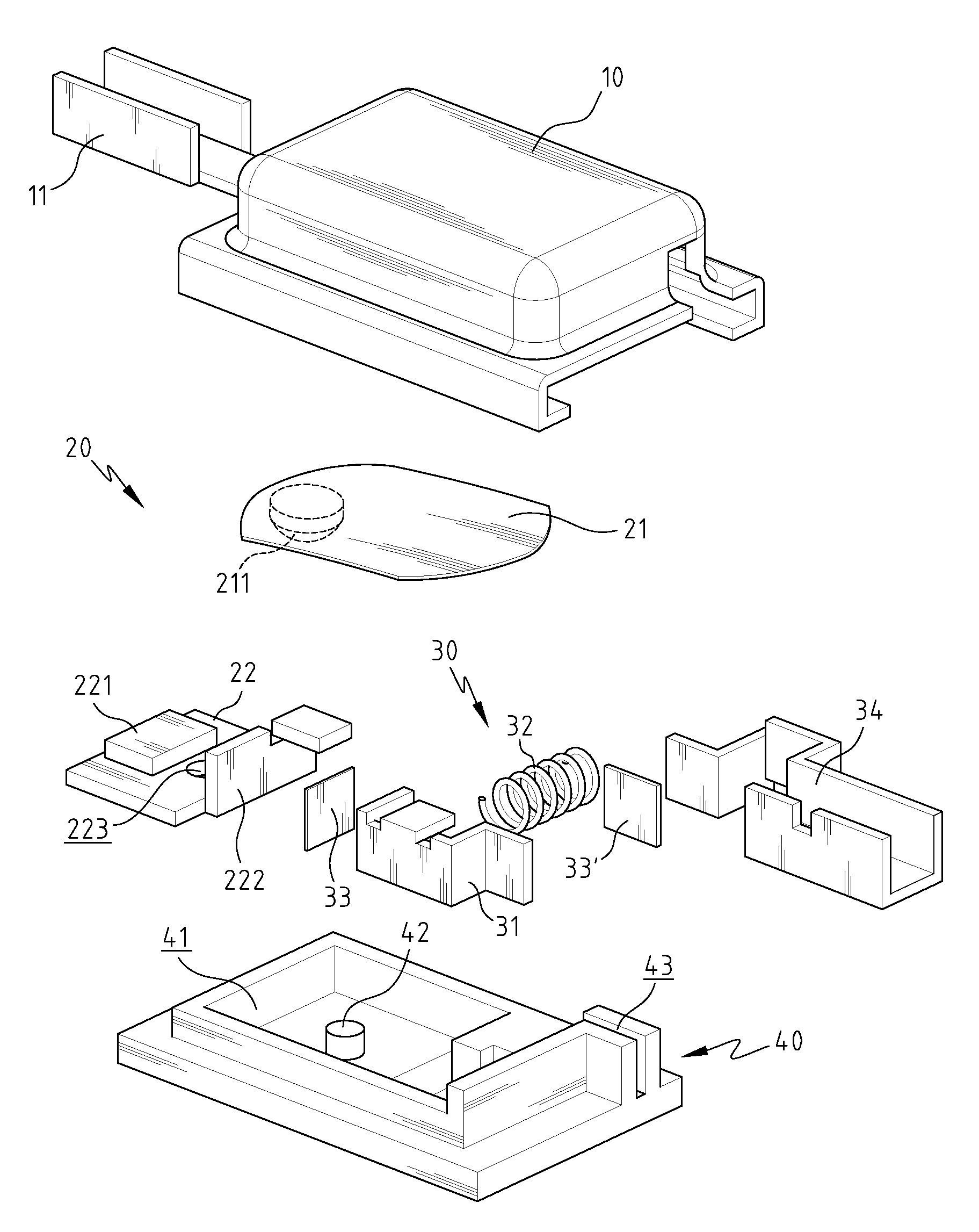
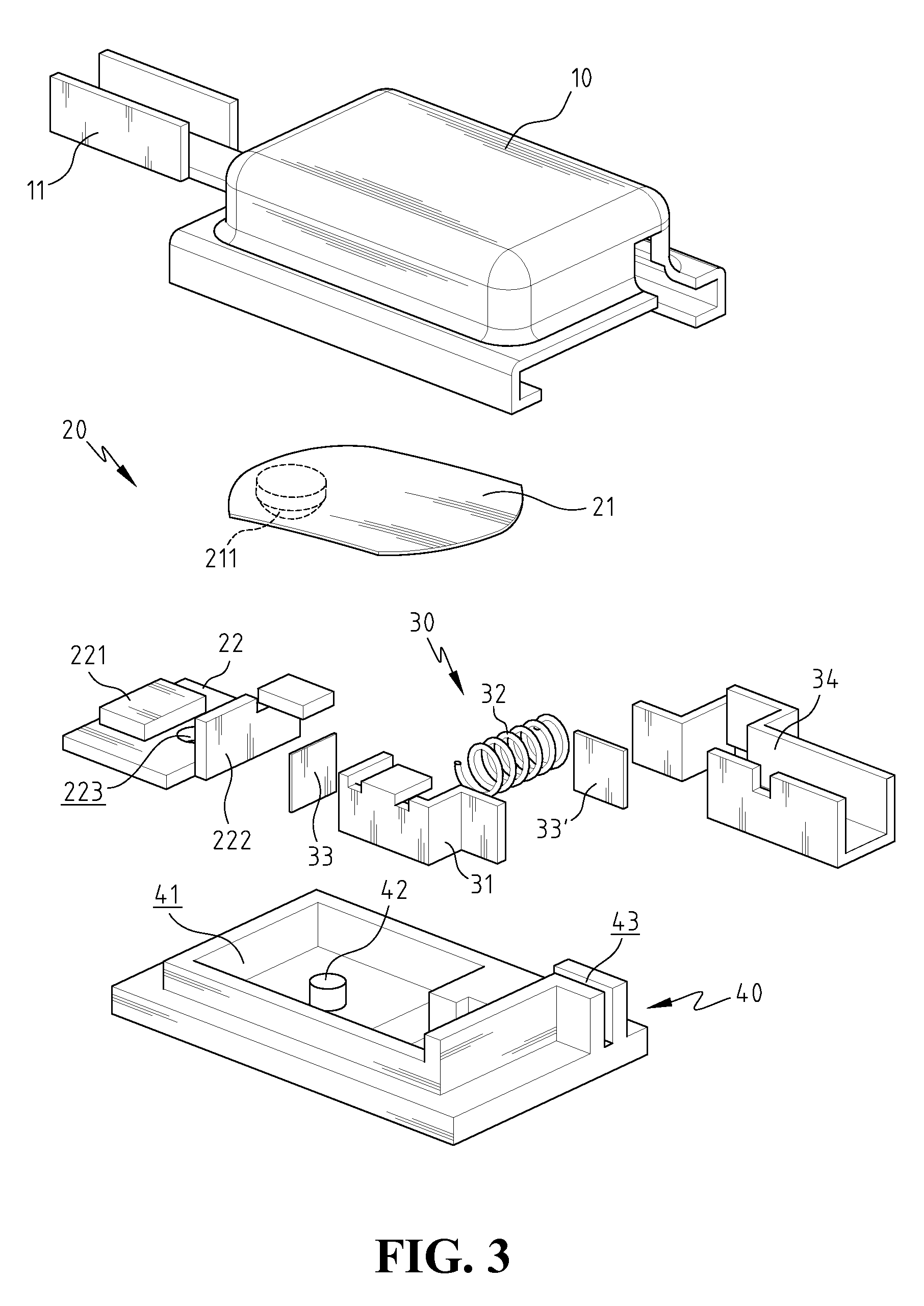
[0024]With reference to FIGS. 3 to 6, a dual protection device for a circuit according to the present invention includes a cover 10, a first protection unit 20, a second protection unit 30 and a base 40.

[0025]The cover 10 is made of a conductive material and has a first terminal 11 connected thereto.

[0026]The first protection unit 20 includes an elastic contact piece 21 and a first conductive member 22. The elastic contact piece 21 is a flexible metal strip. The elastic contact piece 21 is slightly curved in shape and can be bent toward two opposite directions due to temperature change. The elastic contact piece 21 may be made of a bi-metallic material. A first end of the elastic contact piece 21 is fixed to an inner side of the cover 10 and a second end of the elastic contact piece 21 is a free end to bend. The second end of the elastic contact piece 21 is provided with a first contact point 211. The first conductive member 22 is a thin board and a second contact point 221 is dispo...


PUM


Abstract

A dual protection device includes a cover, a first protection unit, a second protection unit and a base. The first protection unit includes an elastic contact piece and a first conductive member. The elastic contact piece has a first end fixed to the cover and a second end including a first contact point. The first conductive member has a second contact point to contact with the first contact point. The elastic contact piece bends to separate the first contact point from the second contact point when overloaded. The second protection unit has a second conductive member, which is respectively connected with the first conductive member and a second terminal by fuse members. A biasing member is compressed between the second conductive member and the base so as to separate the second terminal from the second conductive member when the fuse members melt.

Description

BACKGROUND OF THE INVENTION[0001]1. Field of the Invention[0002]The present invention relates generally to a protection device for a circuit and more particularly, to a dual protection device having two units functioning independently to ensure that the circuit is protected overloaded, overheated, or shorted.[0003]2. The Prior Arts[0004]Electricity plays an import part in everyday life. There are innumerable applications of electricity in the world of today, from computers, home appliances, traffic, and education to entertainment. Therefore, how to use electricity safely is very important.[0005]Generally speaking, a whole circuit includes a main switch which controls the ON and OFF states of the circuit. The main switch has a fuse and / or a circuit breaker to cut off the circuit and prevent the whole circuit from damage, when the circuit is overloaded, overheated, or shorted.[0006]Moreover, the whole circuit may include several sub-circuits and each sub-circuit may have its own switc...

Claims


Application Information

Patent Timeline
IPC IPC(8): H01H85/00H01H37/00H01H31/00H01H61/00H02H9/02
CPCH01H37/002H01H37/5418H01H37/761H01H2037/762
Inventor YU, TSUNG MOU
Owner YU TSUNG MOU
Why Eureka
Try Eureka