Compound bracket system

a bracket system and compound technology, applied in the field of internal combustion engines, can solve the problems of increasing acceleration, affecting the components that are connected thereto, and generating vibrations of engines, and achieve the effect of increasing the rigidity of the second brack

Active Publication Date: 2010-10-12
INT ENGINE INTPROP CO LLC
View PDF9 Cites 34 Cited by
  • Summary
  • Abstract
  • Description
  • Claims
  • Application Information

AI Technical Summary

Benefits of technology

[0008]A compound bracket system for an internal combustion engine includes a first bracket that is rigidly connected to a crankcase of the internal combustion engine. The first bracket forms at least one mounting pad that is arranged to connect to and support a first engine component. A second bracket is connected to the crankcase indirectly through at least one or more additional engine component(s), and thus its connection to the crankcase is not as rigid as that of the first bracket. The second bracket forms a component cavity that is arranged to accept and support a second engine component. The first bracket forms an interconnection pad, and the second component forms a strut having a mounting tab. The mounting tab is advantageously connected to the interconnection pad with a fastener, thus increasing the rigidity of the second bracket as mounted on the engine.

Problems solved by technology

As is known, engines generate vibrations during operation that may negatively affect components that are connected thereto.
Components vibrating at or close to their natural frequency experience increased amplitudes and increased accelerations, both of which are undesirable and detrimental to the component's operation and longevity of service.
Even though brackets that are designed stiffly enough to increase their natural frequency to fall outside of the range of excitation frequencies of the engine are effective at reducing or eliminating excessive vibration of components, such brackets are often relatively larger and heavier than what is required to maintain component mounting in a static condition.
Large and heavy brackets cause an increase in cost of manufacture of an engine and a decrease in fuel economy of the engine due to their larger size and weight.

Method used


Image

  • Compound bracket system
  • Compound bracket system
  • Compound bracket system

Examples


Embodiment Construction

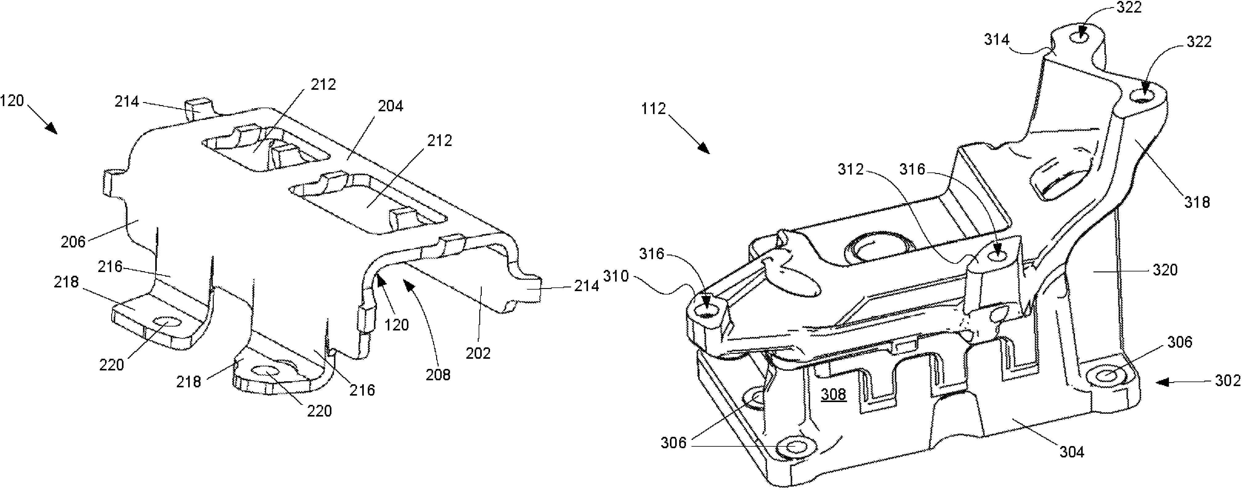
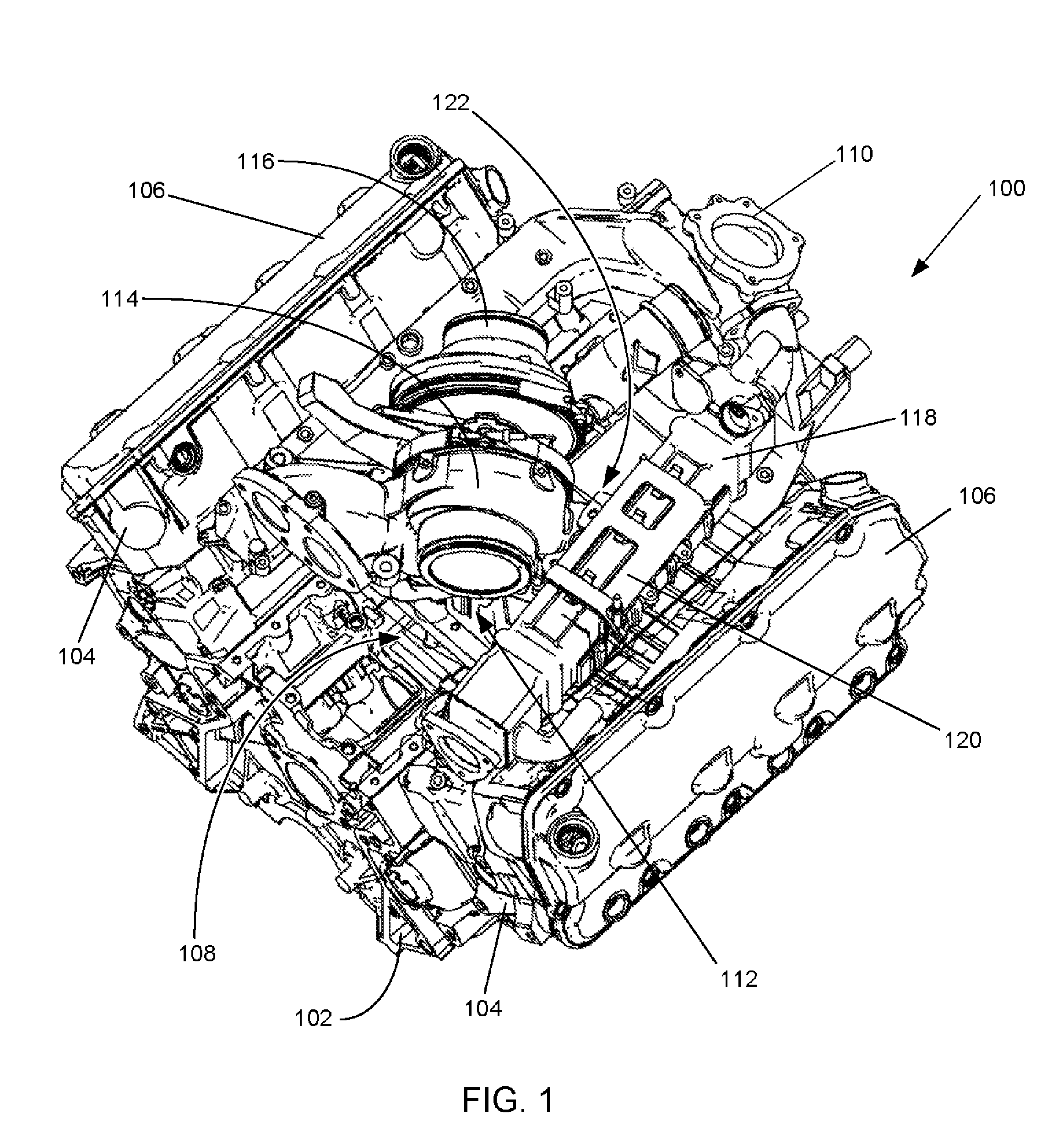
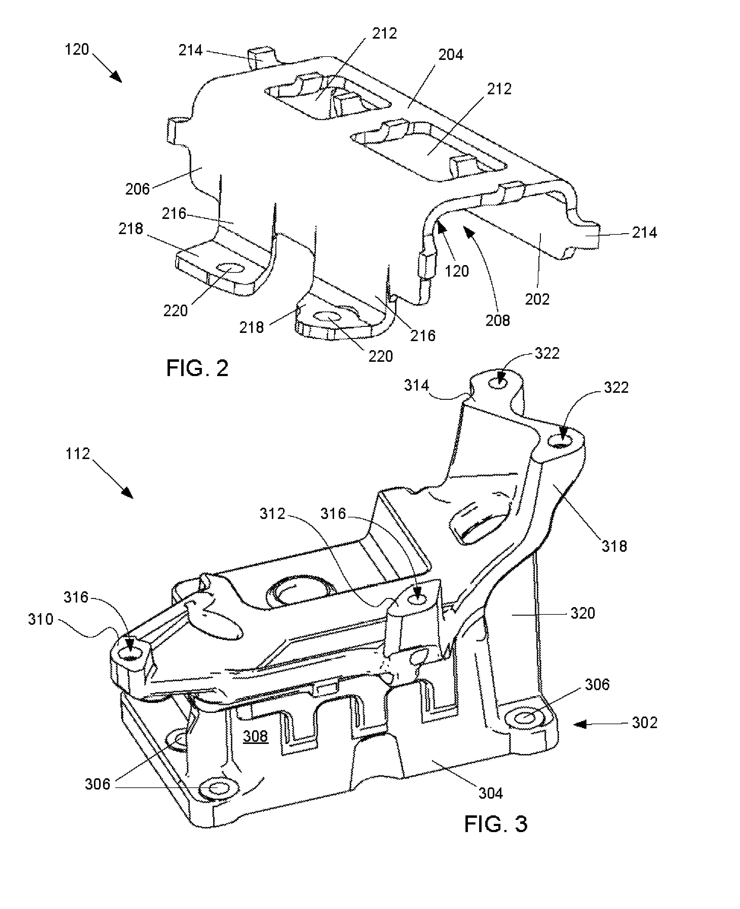
[0013]The following describes an apparatus for mounting components onto an internal combustion engine. In a preferred embodiment, the apparatus includes a compound bracket system that is capable of rigidly mounting various engine components onto an engine such that a natural frequency of the components and the bracket system is outside of an excitation frequency range of the engine during operation. The bracket system is advantageously light and simple as compared to known bracket systems that are used to rigidly mount components onto engines.

[0014]An outline view of an internal combustion engine 100 is shown in FIG. 1. The engine 100 shown has two banks of cylinders arranged in a “V” configuration, but as it will become evident to one having skill in the art, the advantages of this invention may be realized for engines having other configurations, for example, engines having cylinders arranged in an inline or “I” configuration. The engine 100 includes a base engine structure or cra...


PUM


Abstract

A compound bracket system (400) for an internal combustion engine (100) includes a first bracket (112) that is rigidly connected to a crankcase (102) of the internal combustion engine (100). The first bracket (112) forms at least one mounting pad (310) that is arranged to connect to and support a first engine component (114). A second bracket (120) is connected to the crankcase (102) through at least one additional engine component (110). The second bracket (120) forms a component cavity (208) that is arranged to accept and support a second engine component (118). The first bracket (112) forms an interconnection pad (314), and the second component forms a strut (216) having a mounting tab (218). The mounting tab (218) is advantageously connected to the interconnection tab (314) with a fastener (422), thus increasing the rigidity of the second bracket (120) as mounted on the engine (100).

Description

FIELD OF THE INVENTION[0001]This invention relates to internal combustion engines, including but not limited to structures, or brackets, used to connect various components of the engine to an engine support structure.BACKGROUND OF THE INVENTION[0002]Support structures, commonly referred to as brackets, that are used to connect various engine components to other components on the engine are known. Brackets are typically used to mount onto a base engine structure, for example a crankcase, other engine components that are necessary for the operation of the engine. Such components that are typically mounted onto the base engine structure include turbochargers, Exhaust Gas Recirculation (EGR) coolers, oil coolers, electronic control modules (ECM), oil filters, and so forth.[0003]Brackets used to mount components onto an engine are typically designed to comport with appropriate specifications that require that the mounting of the component does not subject the components to excessive vibr...

Claims


Application Information

Patent Timeline
Patent Type & Authority Patents(United States)
IPC IPC(8): F16M1/00F02B33/00
CPCF02B67/10F02M25/0703F02M26/12
Inventor PREIMESBERGER, ERICH R.FENTON, DONALD M.KOPPIREDDY, TRINADHKRISHNASWAMI, JAYAKUMARWU, MARTINTAO, ZEGUANGMIGNERY, LEZZA
Owner INT ENGINE INTPROP CO LLC
Why Eureka
Try Eureka