
Actuable load carrier cradle

a load carrier and actuation technology, applied in the field of carriers, can solve the problems of detriment to users, load carriers suffering from deficient design, and significant restrictions in the use of such carriers, and achieve the effect of improving the compatibility and the usefulness of carriers

Active Publication Date: 2010-10-12
THULE SWEDEN AB
View PDF20 Cites 24 Cited by
  • Summary
  • Abstract
  • Description
  • Claims
  • Application Information

AI Technical Summary

Benefits of technology

[0014]In an alternative configuration, the invention takes the form of a method for providing a load carrier arrangement for transporting a bicycle when secured thereupon. The method comprises utilizing a load carrier arrangement having a frame assembly mounted to a carrying vehicle and that includes an elongate arm configured to receive a bicycle cradle thereupon to transport a bicycle. The bicycle cradle is operator configurable (can be changed from one to the other) between a bicycle transporting configuration in which the cradle is tight-fitting upon the arm and a non-transporting configuration in which the cradle is comparably loose-fitting upon the arm. At least one step contemplated with regard to this embodiment of the invention includes reconfiguring the bicycle cradle to the non-transporting configuration after transporting use (carrying a bicycle on the carrier) and thereby limiting strain induced, cold-flow creep in the bicycle cradle that results in a reduction of tightness of fit of the cradle upon the arm to periods when the bicycle transporting configuration is assumed.
[0044]In summary, inclusion of one or more of the above described features in a sports equipment carrier enhances the carrier's usefulness, its compatibility with variably configured carrying vehicles, and its ease of manufacture, installation and use.

Problems solved by technology

If the configuration of the carrier were fixed, the utilization of such a carrier would be significantly restricted.
Another aspect of such load carriers often suffering from deficient design is the cradle upon which the bicycles rest, and by which the bicycles are secured to the carrier.
Because of the cradle's typical construction from predominantly hard plastic, a problem arises and is rooted in the well appreciated (by those persons skilled in the technicalities of material science) phenomenon of cold-flow “creep” or “compressive set”.
The detriment to the user is that the cradle now has either little or no resistance to movement on the arm, which translates into an inability to hold-fast an article positioned in the cradle relative to the balance of the incorporating carrier.
These detrimental effects can include accentuated swinging or translational movement of the carried articles which can scratch the transporting vehicle, or worse, if not prevented by an interference component such as an end cap, the cradle, including whatever it is carrying (bicycle) may slide free of the arm and be lost from the vehicle.
This, however, is an inadequate solution in that it not only fixes longitudinal movement of the cradle along the length of the arm (but which is sometimes desired), but rotational movement of the cradle on the arm is also prevented, and which is often similarly desired by the user.

Method used


Image

  • Actuable load carrier cradle
  • Actuable load carrier cradle
  • Actuable load carrier cradle

Examples


Embodiment Construction

[0079]As required, detailed embodiments of the presently disclosed inventions are described herein; however, it is to be understood that the disclosed embodiments are merely exemplary of the inventions that may be embodied in various and alternative forms. The figures are not necessarily to scale, some features may be exaggerated or minimized to show details of particular components. Therefore, specific structural and functional details disclosed herein are not to be interpreted as limiting, but merely as a basis for the claims and as a representative basis for teaching one skilled in the art to variously employ the inventions.

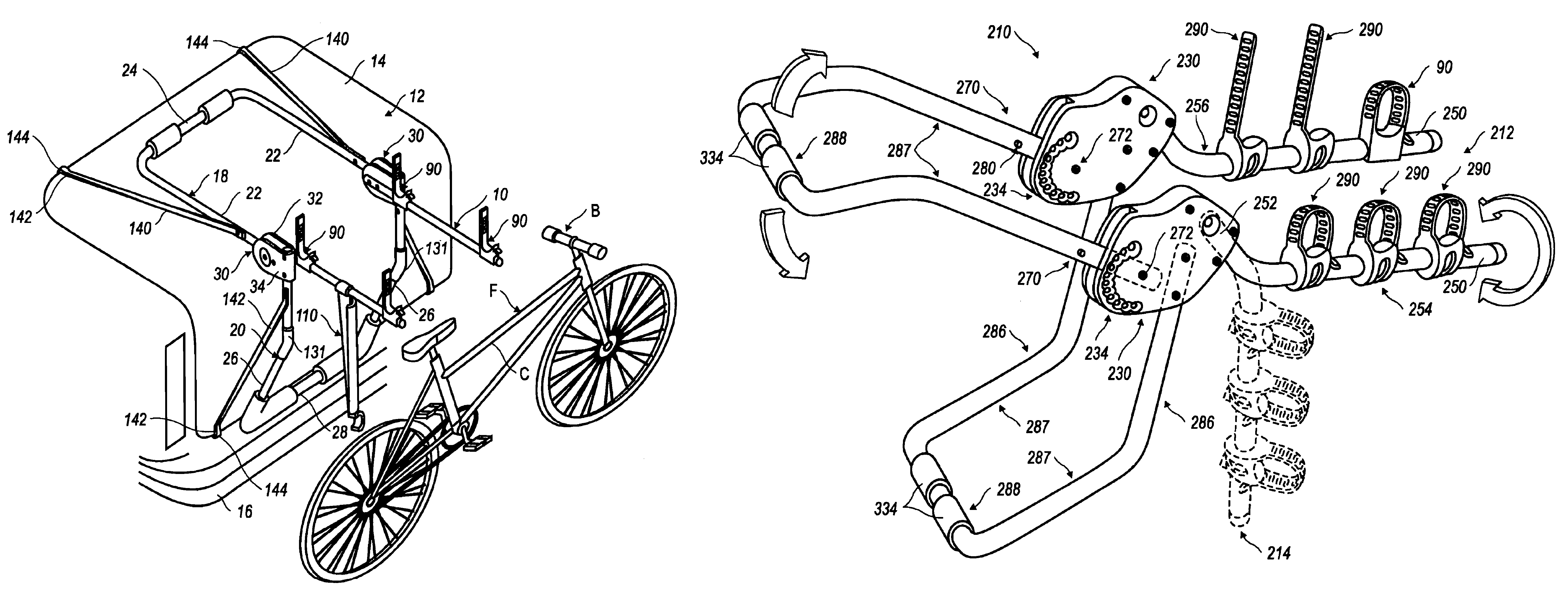
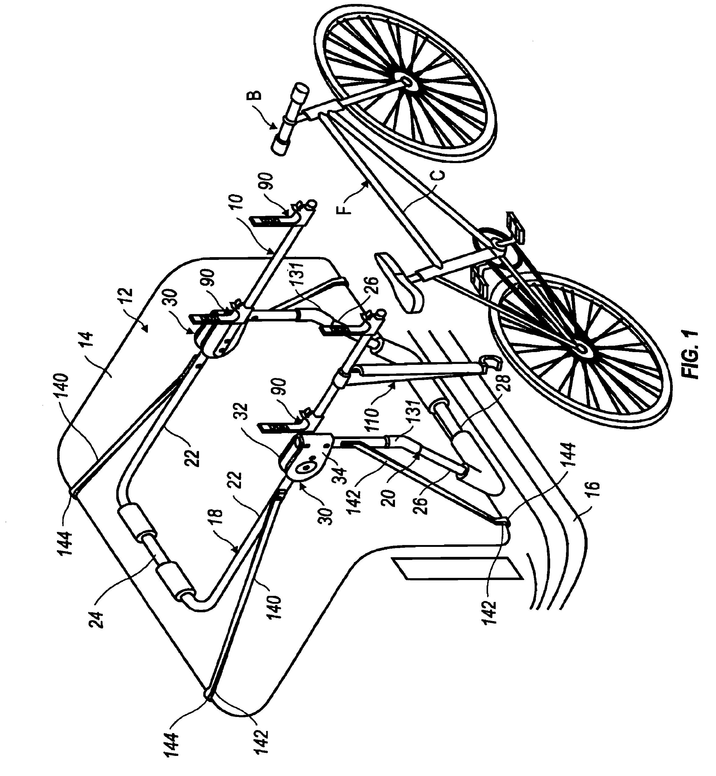
[0080]Referring to the Figures, one exemplary embodiment of a bicycle carrier 10 is shown in FIG. 1 as being mounted on the rear of a vehicle 12. The vehicle 12 includes a trunk lid 14 and a bumper 16.

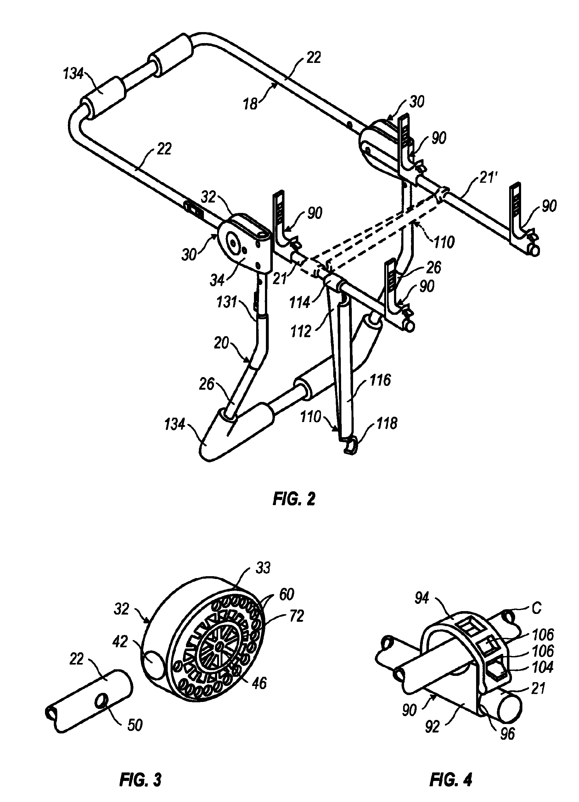
[0081]The carrier 10 comprises a frame formed by a pair of mounting members 18, 20, and a pair of bicycle supporting arms 21, 21′ project rearwardly from the fra...


PUM


Abstract

Method and apparatus for providing a load carrier arrangement for transporting a bicycle when secured thereupon. The load carrier arrangement including a frame assembly adapted to be mounted to the carrying vehicle. The frame assembly has at least one elongate arm configured to receive a bicycle cradle thereupon. The bicycle cradle is mounted upon the arm and is operator configurable between a bicycle transporting configuration and a non-transporting configuration. The cradle has a through-passage within which the elongate arm is received and the cradle is operator reciprocal on the elongate arm in the non-transporting configuration thereby facilitating variable longitudinal positioning of the cradle by the operator upon the arm. The cradle has an increased resistance to longitudinal reciprocation on the elongate arm in the bicycle transporting configuration in comparison to the non-transporting configuration. In this manner, the cradle is effectively longitudinally fixed on the elongate arm in the bicycle transporting configuration to an extent that a secured portion of a carried bicycle in the cradle is longitudinally fixed relative to the elongate arm during transport on the load carrier arrangement.

Description

CROSS-REFERENCE TO RELATED APPLICATIONS[0001]The present application is a continuation-in-part patent application of U.S. application Ser. No. 10 / 032,122 filed Dec. 31, 2001, now U.S. Pat. No. 6,772,927; said application, in its entirety being hereby expressly incorporated by reference into the present application.TECHNICAL FIELD[0002]The present invention relates generally to carriers mountable to vehicles for transporting sports equipment. More particularly, it relates to carriers, often mountable to a rear end of a vehicle, and for transporting bicycles thereon.BACKGROUND ART[0003]Many types of sports equipment are useable only under certain conditions and / or in specific locales. Examples of such sports equipment include surfboards that are ridden at beaches and snow skis that are normally used at ski resorts. The beach and ski areas are often remotely located from the homes of those who use them, Therefore, the need for transporting sports equipment upon vehicles to these locati...

Claims


Application Information

Patent Timeline
Patent Type & Authority Patents(United States)
IPC IPC(8): B60R9/00F16L3/22A47F7/00B60R11/00F16L5/00B60R9/06B60R9/10
CPCB60R9/06B60R9/10
Inventor BOVE, VINCENTBOGOLOFSKI, KEVINRIEHM, GEORGEWEAVER, GREGOR
Owner THULE SWEDEN AB
Learn More