Implant device for applying compression across a fracture site

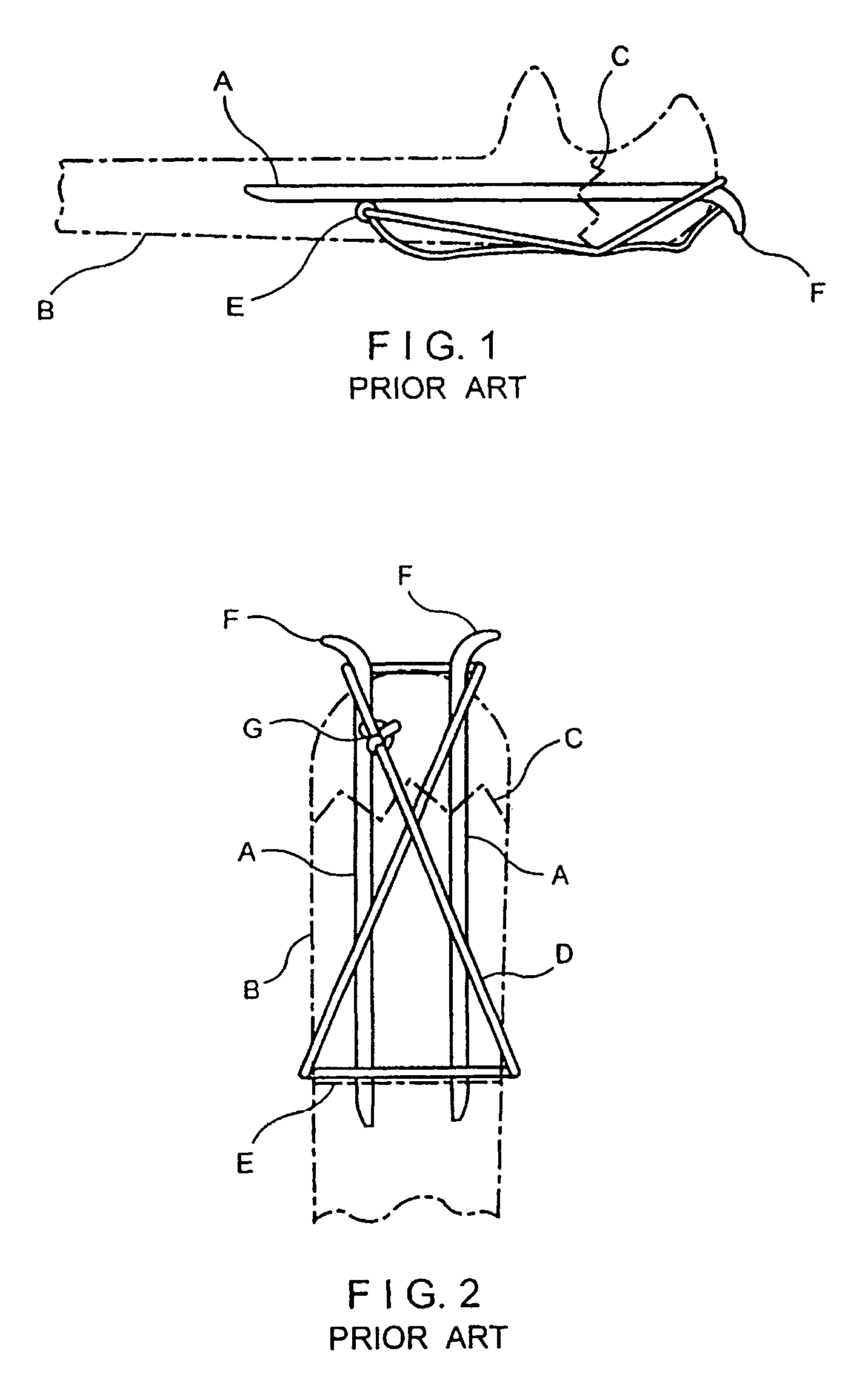
a technology for fractures and implants, applied in the direction of osteosynthesis devices, prostheses, surgical staples, etc., can solve the problems of cumbersome passage of wire through drill holes d, through tendon and under pins, and irritation of soft tissues

Inactive Publication Date: 2010-10-12
MEDOFF ROBERT J +2
View PDF29 Cites 65 Cited by
  • Summary
  • Abstract
  • Description
  • Claims
  • Application Information

AI Technical Summary

Benefits of technology

[0010]An object of the invention is to provide an implant device which overcomes the above problems and disadvantages by avoiding the use of the stiff pins that may protrude from the bone and providing a continuous length of wire to apply the compressive force across the fracture site.
[0013]Another object of the invention is to provide a simplified embodiment which is reliable, easy to manufacture and avoids the use of washers to secure the fixation element to the implant.
[0018]In further accordance with the invention, the bend portion has a small enough cross-section to facilitate bending of the implant while providing resilience of the implant at the bend.

Problems solved by technology

One problem with this standard FIG. 8 tension band wiring occurs because standard large pins A are used which protrude from the end of the bone at F at the location where a major tendon inserts.
Because of this, the ends F of the pins frequently cause irritation of the soft tissues and require removal.
A minor technical problem with the standard FIG. 8 tension band wiring is that the passage of the wire through drill hole D and through the tendon and under the pins can be cumbersome.
Another problem with standard FIG. 8 tension band wiring is that there is no physical connection between the stiff intramedullary pin and the extraosseous wire.
As a result, this construct has little resistance to rotation at the fracture site.

Method used


Image

  • Implant device for applying compression across a fracture site
  • Implant device for applying compression across a fracture site
  • Implant device for applying compression across a fracture site

Examples


Embodiment Construction

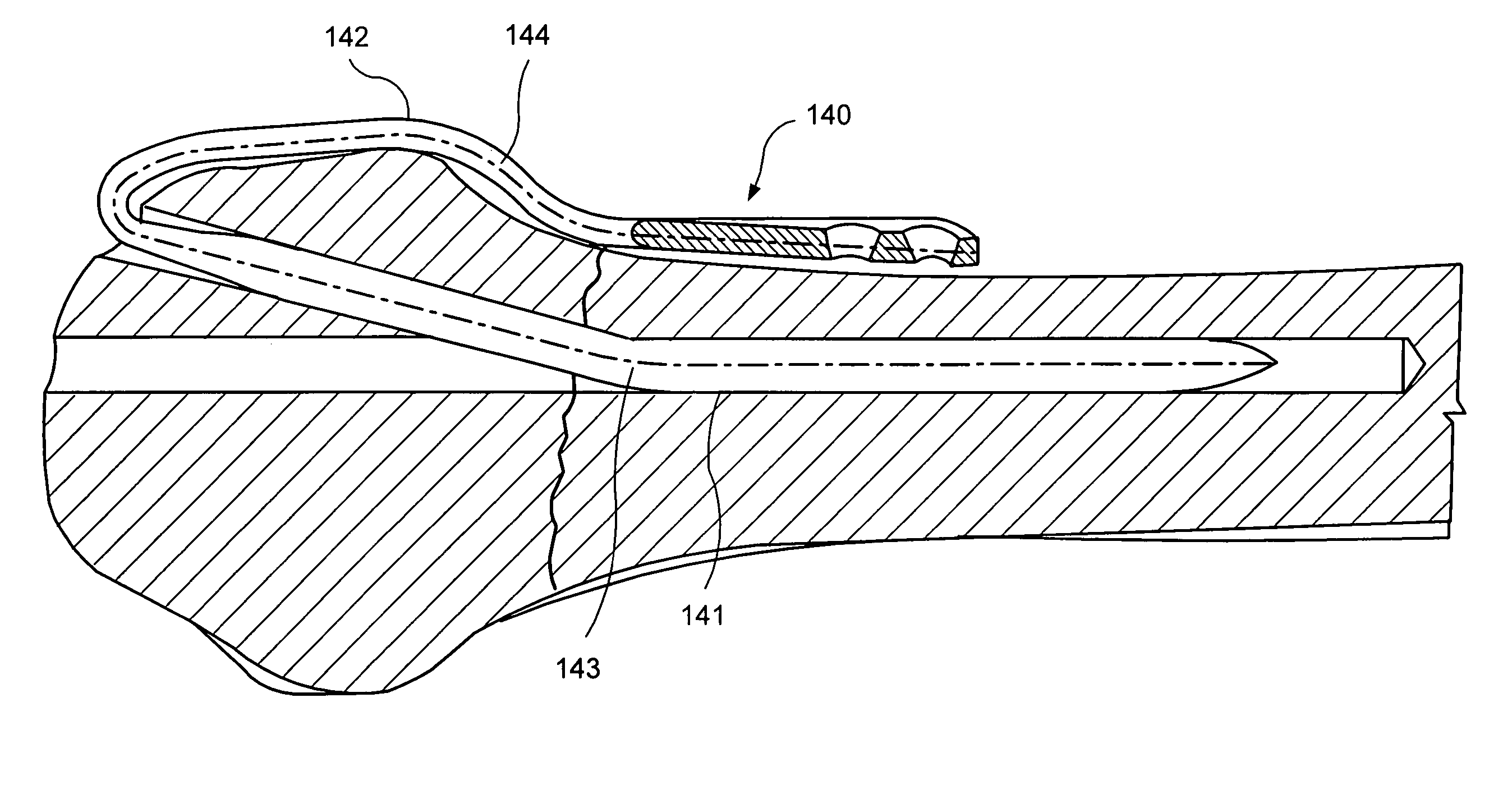
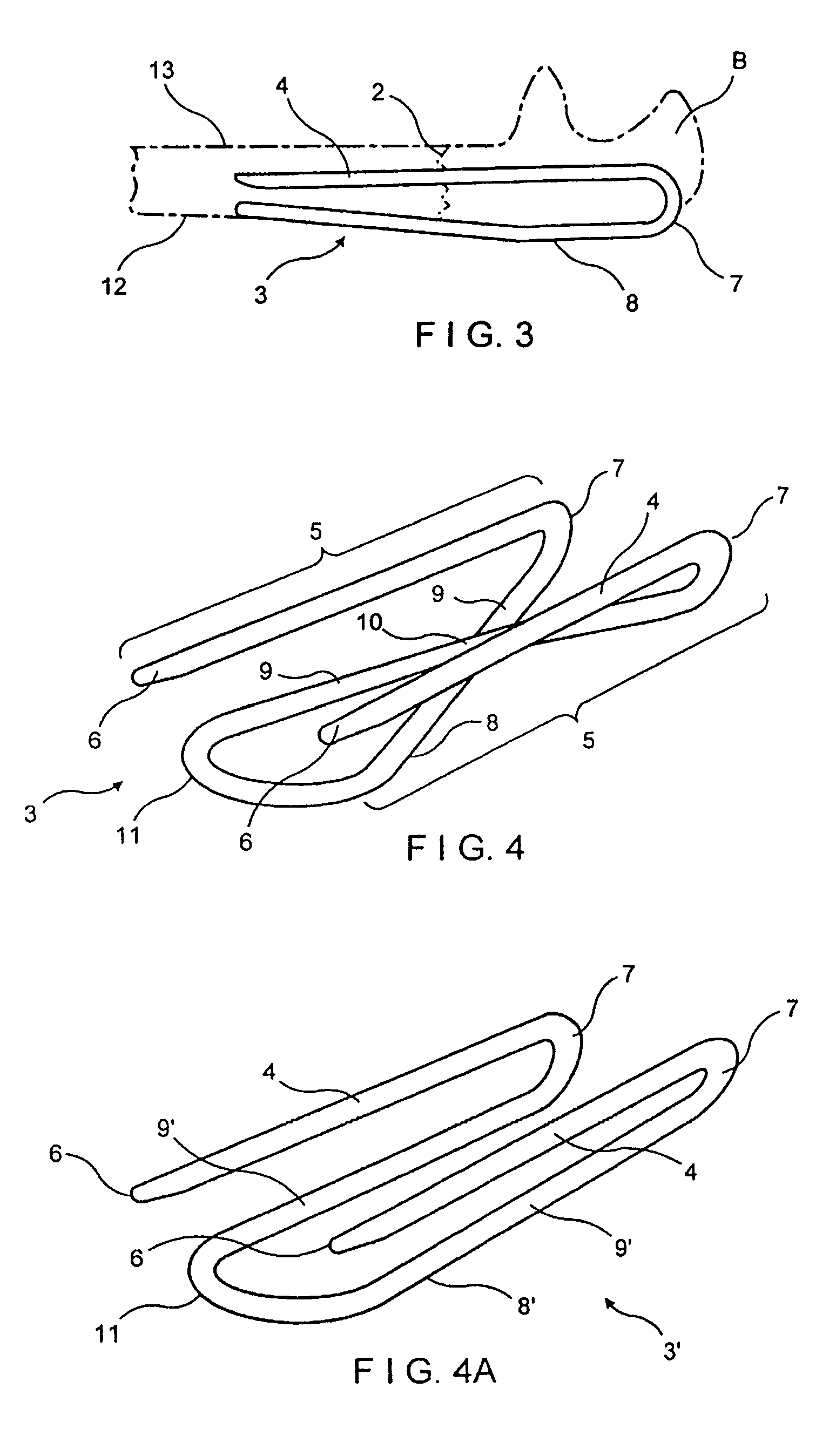
[0074]The drawings illustrate a fracture fixation implant device 1 for applying compression across a fracture 2 in a bone B. The bone B, for example, may be the olecranon or the patella that involve an articular surface.

[0075]The implant device 1 comprises a continuous wire element 3 formed with two spaced longitudinally extending legs 4 which are adapted to be driven into the bone B across the fracture 2. The term “wire” or “wire element” is an art recognized term and covers elements having circular or rectangular cross-sections and commonly referred to as pins, wires or bars. The legs 4 form a first portion 5 of the wire element and the legs 4 extend at their ends remote from free ends 6 thereof to bend portions 7 extending outside the bone. Integrally connected to bend portions 7 is a second portion 8 extending backwardly from the bend portions 7 in juxtaposition with the legs 4 of the first portion 5. The second portion 8 includes legs 9 continuous with respective bend portions ...


PUM


Abstract

A fracture fixation implant formed from a single piece of material bent in loop form to provide juxtaposed first and second legs joined by a bend. The first leg is dimensional and configured to be implanted within a bone to extend across a fracture in the bone, the second leg extending backwardly from the bend and having a length to extend on an outer surface of the bone across the fracture. The implant exits from the bone at the bend, such that application of a pulling force on the second leg produces compression across the fracture. The second leg is flat and is provided with a plurality of holes in which bone screws can be installed to secure the second leg directly to the bone and maintain the compression across the fracture. The implant avoids the use of washers.

Description

CROSS RELATED APPLICATION[0001]This application is a C-I-P of application Ser. No. 10 / 073,826 filed Feb. 11, 2002, now U.S. Pat. No. 7,037,308 which claims the benefit of Provisional Application Ser. No. 60 / 268,099 filed Feb. 12, 2001.FIELD OF THE INVENTION[0002]The invention relates to an implant device for applying compression across a fracture site in a bone and in particular to such an implant device which is constructed as a wire element which is used without separate pins.BACKGROUND AND PRIOR ART[0003]By way of example, fractures of the olecranon (upper end of the ulna at the level of the elbow) and fractures of the patella (kneecap) are fractures that involve an articular surface. Restoration of the joint surface to anatomic alignment is the accepted method of fixation.[0004]Both the olecranon and patella are loaded during joint flexion. The deep articular surface is loaded in longitudinal compression by the reactive forces across the articular surface; the superficial bone s...

Claims


Application Information

Patent Timeline
Patent Type & Authority Patents(United States)
IPC IPC(8): A61B17/58A61B17/68A61B17/88
CPCA61B17/68A61B17/7208A61B17/7225A61B17/7233A61B17/8869
Inventor MEDOFF, ROBERT J.
Owner MEDOFF ROBERT J
Why Eureka
Try Eureka