

Optical fiber cable
a technology of optical fiber and fiber optic cables, applied in the field of optical fiber optic cables, can solve the problems of damage to optical fibers and the risk of increasing the transmission loss of optical fibers, and achieve the effect of preventing increased transmission loss
Inactive Publication Date: 2010-10-12
FURUKAWA ELECTRIC CO LTD
View PDF14 Cites 11 Cited by
- Summary
- Abstract
- Description
- Claims
- Application Information
AI Technical Summary
Benefits of technology
The present invention provides an optical fiber cable that can prevent increased transmission loss due to damage caused by the egg-laying behavior of cicadas. This is achieved by using a sheath with a hardness of at least 55 and a minimum distance of 0.3 mm between the sheath and the optical fiber. The sheath is made of a flame retardant composition that includes a thermoplastic resin, a metal hydrate, and red phosphorus. The cable may also have a carbon added to the flame retardant composition. This invention ensures reliable prevention of transmission loss and improves the durability of optical fiber cables.
Problems solved by technology
However, even in this kind of optical fiber cable, the ovipositor may avoid the protective tape and cut through at an angle, thereby causing damage to the optical fiber.
As a result, there is the risk of incurring increased transmission loss of the optical fiber.
Method used
View moreImage
Smart ImageViewing Examples

Examples
examples
[0124]The present invention will now be described more specifically and in more detail with the second test examples. However, the present invention is not limited to these examples. Further, unless otherwise noted, the term “parts” representing the composition indicates “parts by mass”.
Login to View More PUM
 Abstract
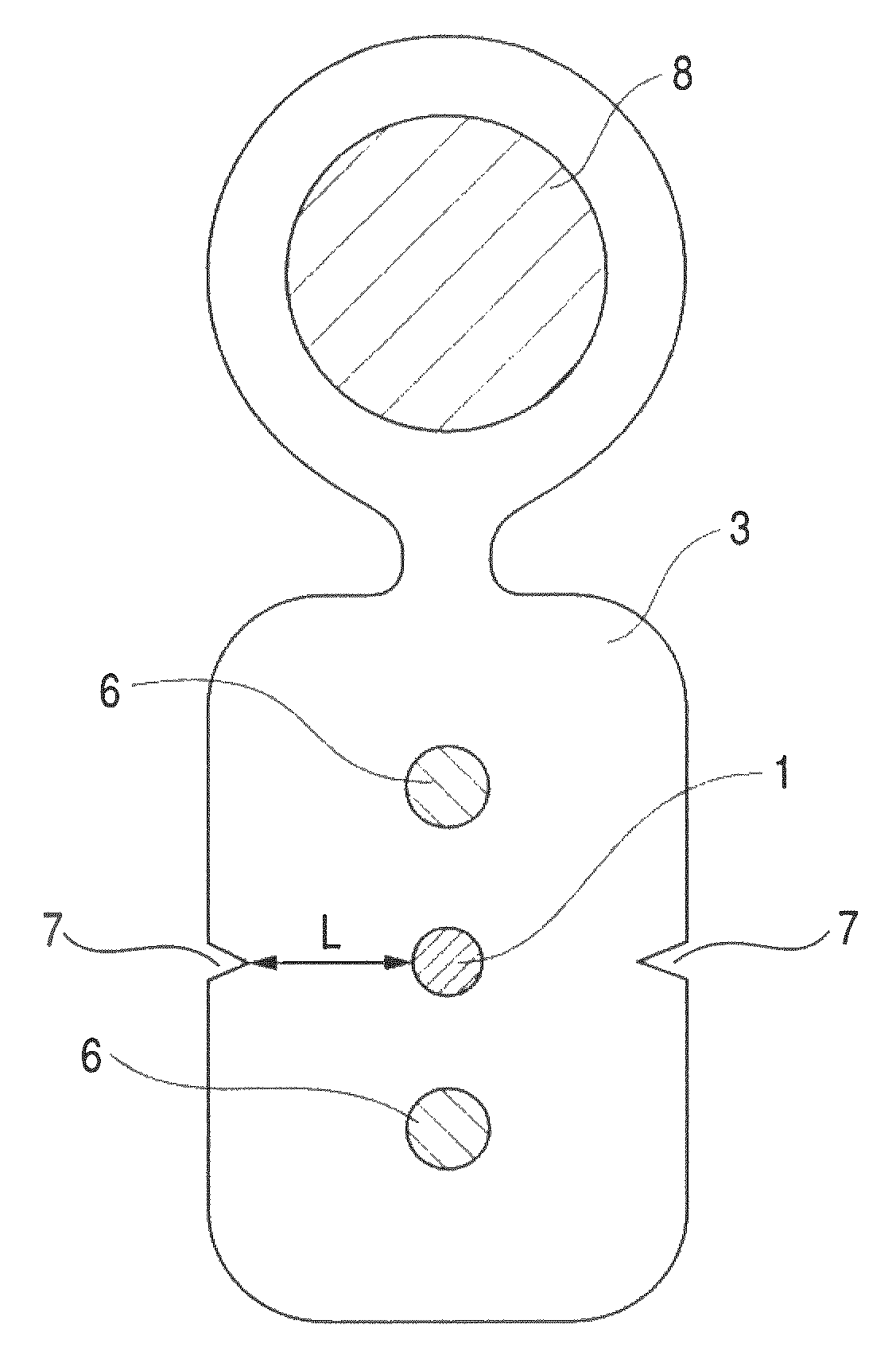
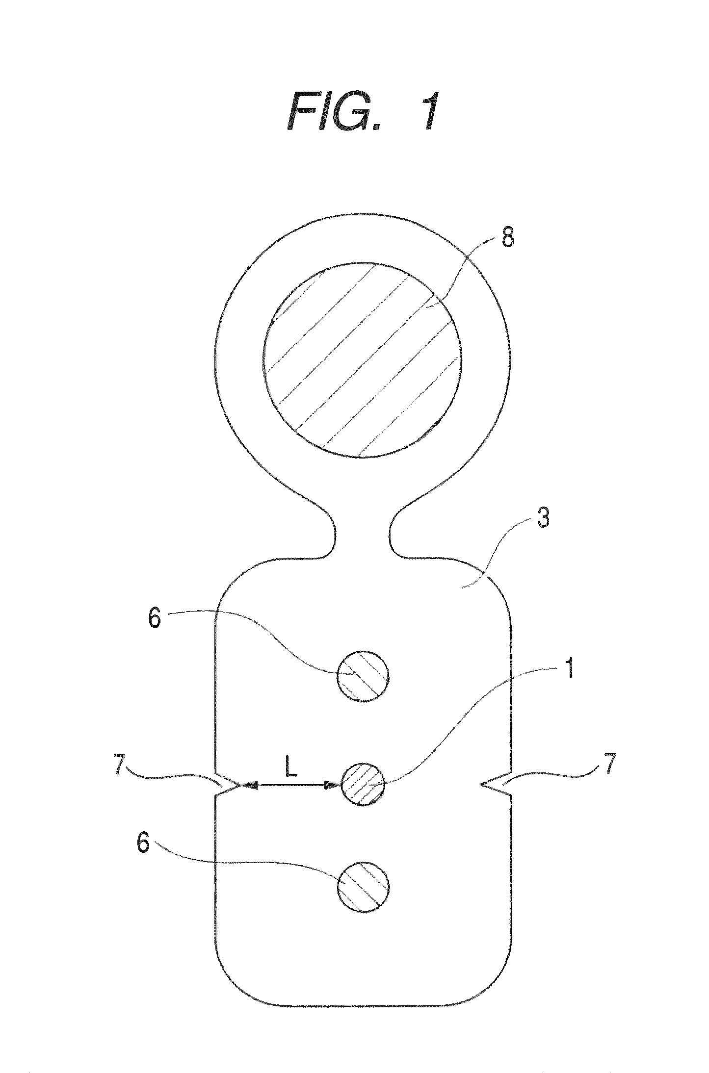
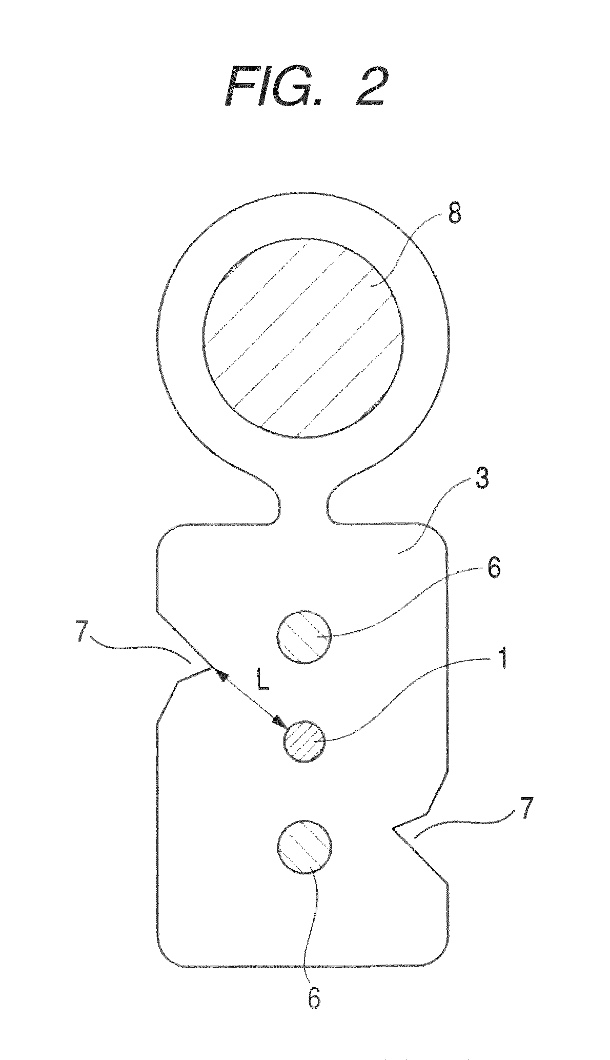
It is an object of the present invention to provide an optical fiber cable which can reliably prevent increased transmission loss due to damage of the optical fiber as a result of the egg-laying behavior of cicadas. The cable includes at least an optical fiber 1, tension members 6 and a sheath 3. The sheath 3 has a shore D hardness of 55 or more and a minimum distance L from a surface of the optical fiber 1 to an outer surface of the sheath 3 of greater than 0.3 mm. Further, in the cable, the surface of sheath 3 has a coefficient of friction of 0.45 or less and the sheath 3 has a shore D hardness of 57 or more. In addition, the cable is made by using a specific flame retardant composition (P) as the sheath material.
Description
CROSS-REFERENCES TO RELATED APPLICATIONS[0001]This application is a continuation-in-part application of PCT / JP2008 / 050797, international application filed Jan. 22, 2008 designating the United States of America, and claims the benefit of PCT / JP2008 / 050797. The entire content of this application is incorporated herein by reference.[0002]This application also claims the benefit of priority from Japanese Patent Application No. 2007-013222 filed Jan. 24, 2007, No. 2007-013202 filed Jan. 24, 2007, No. 2007-014146 filed Jan. 24, 2007 and No. 2007-014154 filed Jan. 24, 2007, the entire contents of which are incorporated herein by reference.TECHNICAL FIELD[0003]The present invention relates to an optical fiber cable having an optical fiber and tension members inside a sheath.BACKGROUND ART[0004]Conventionally, various optical fiber cables have been produced and used. Such optical fiber cables are produced by, for example, preparing a so-called optical fiber, which has a coating composed of a...
Claims
Login to View More Application Information
Patent Timeline
 Patent Type & AuthorityPatents(United States)
IPC IPC(8): G02B6/44
CPCG02B6/443G02B6/4433G02B6/4436
InventorYASUTOMI, TETSUYATSUKAMOTO, MASAYOSHIIWANO, MITSURURINTSU, YOSHIHISAARAGAKI, MASANOBUNISHIGUCHI, MASAKI
OwnerFURUKAWA ELECTRIC CO LTD