Optical fiber

a technology of optical fiber and lateral pressure, applied in the field of optical fiber, can solve the problems of deterioration of increase in transmission loss, and poor resistance of optical fiber to lateral pressure, and achieve excellent resistance to lateral pressure and low-temperature characteristics, and reduce the modulus of young

Active Publication Date: 2017-01-05
SUMITOMO ELECTRIC IND LTD
View PDF5 Cites 10 Cited by
  • Summary
  • Abstract
  • Description
  • Claims
  • Application Information

AI Technical Summary

Benefits of technology

[0011]The glass fiber included in the optical fiber of the present invention is a multimode fiber which is excellent in terms of resistance to later...

Problems solved by technology

Reducing the glass-fiber diameter of optical fibers results in a deterioration in resistance to lateral pressure.
This is because when lateral pressure is applied to the optical fiber, micro-bending occurs at the interface between the core and the cladding to cause an increase in transmission loss.
Especially in the case of using a multimode fiber as the glass fiber, the optical fiber shows poorer resistance to lateral pressure as compared with the case of using...

Method used


Image

  • Optical fiber
  • Optical fiber
  • Optical fiber

Examples


examples

[0063]The results of evaluation tests to which Examples according to the present invention and Comparative Examples were subjected are shown below to explain the present invention in more detail. The present invention should not be construed as being limited to the following Examples.

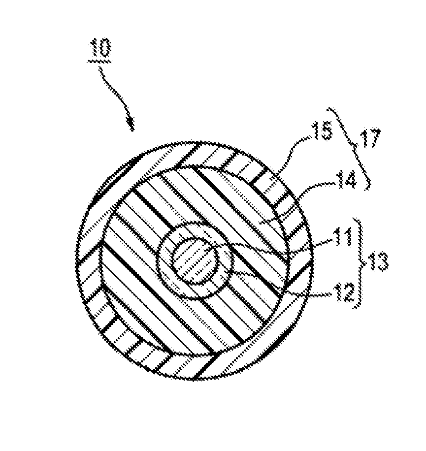
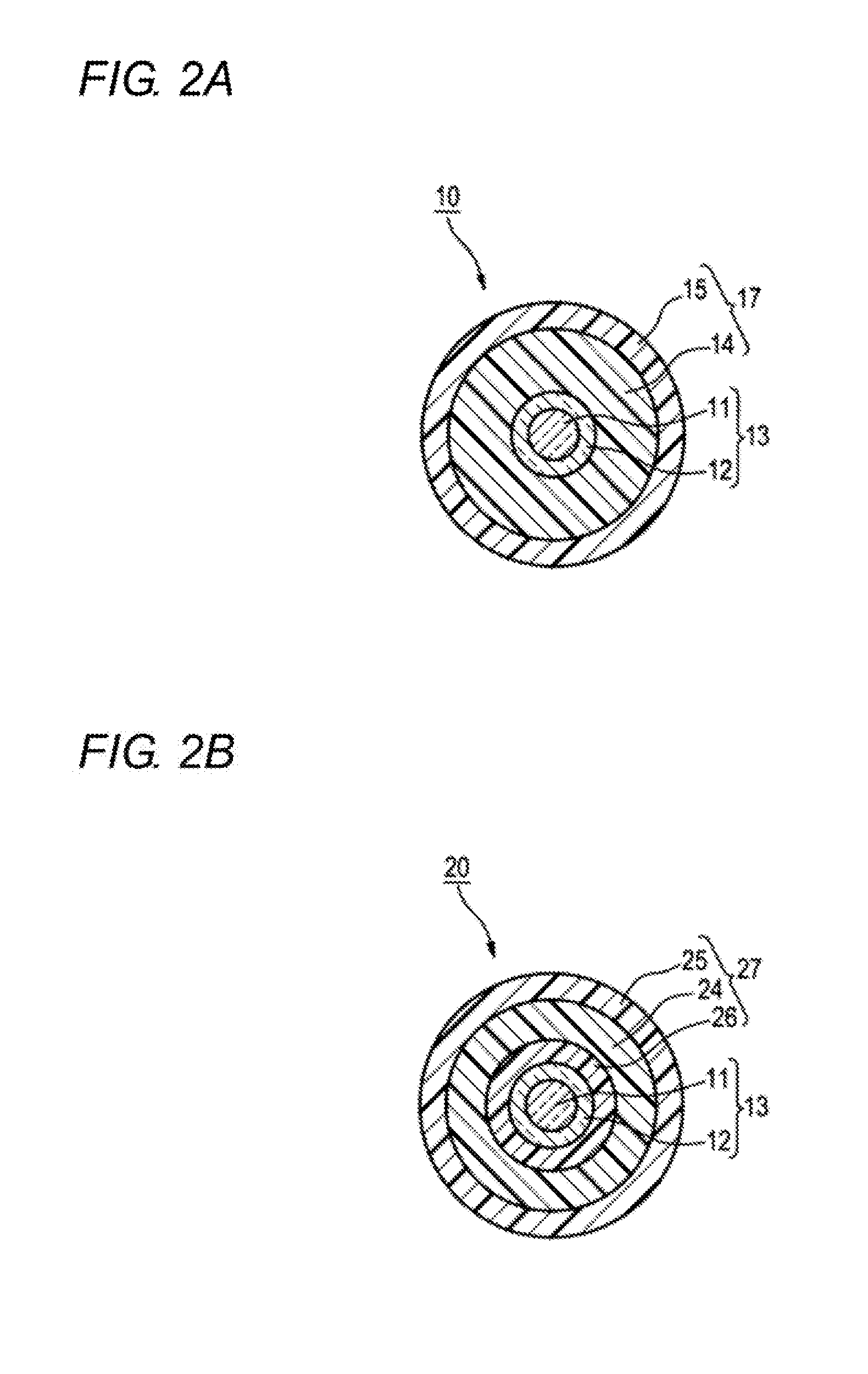
Production of Optical Fibers 10 and 20

[0064]As glass fibers 13, use was made of glass fibers which each had a core diameter of 50 μm, a cladding diameter in the range (90-110 μm) shown in Tables 1 and 2, and a refractive index profile shown in the Tables 1 and 2. The resin composition for forming a non-strippable resin coating layer, resin composition for inner-layer formation, and resin composition for outer-layer formation which respectively had the makeups shown below were applied to the peripheral surface of each glass fiber 13 and cured to form resin coating layers. Thus, optical fibers were produced. In the optical fibers each including the non-strippable resin coating layer, the outer diameter of...


PUM

PropertyMeasurementUnit
Lengthaaaaaaaaaa
Lengthaaaaaaaaaa
Percent by massaaaaaaaaaa

Abstract

An optical fiber comprises a glass fiber which comprises a core and a cladding, a primary resin coating layer which covers the periphery of the glass fiber, and a secondary resin coating layer which covers the periphery of the primary resin coating layer. The glass fiber is a multimode fiber having a core diameter of 40-60 μm and a cladding diameter of 90-110 μm, and the primary resin coating layer is a layer formed by curing a curable resin composition which comprises oligomers, monomers, and a reaction initiator, the curable resin composition containing a one-end-capped oligomer in an amount of 30% by mass or larger based on all the oligomers.

Description

CROSS-REFERENCE TO RELATED APPLICATION[0001]The present application claims the benefit of priority of Japanese Patent Application No. 2015-095987, filed on May 8, 2015, which is incorporated herein by reference.BACKGROUND[0002]Technical Field[0003]The present invention relates to an optical fiber.[0004]Related Art[0005]In the field of interconnecting, optical fibers are required to have such fatigue resistance that even when the optical cable is bent to, for example, a radius as small as 1.5-2 mm, the optical fiber in this optical cable is less apt to fatigue.[0006]For obtaining satisfactory fatigue resistance, it is effective to reduce the glass-fiber diameter of the optical fiber. Although optical fibers usually have a glass-fiber diameter of 125 μm, use of an optical fiber having a glass-fiber diameter smaller than 125 μm can improve the fatigue resistance (see, for example, Japanese Patent No. 3902201, Japanese Patent No. 3518089, and U.S. Pat. No. 8,189,978).[0007]Japanese Pate...

Claims


Application Information

Patent Timeline
IPC IPC(8): G02B6/02G02B6/036C03C25/10G02B6/028
CPCG02B6/0288C03C25/1065G02B1/14G02B6/02395
Inventor HOMMA, YUYA
Owner SUMITOMO ELECTRIC IND LTD
Why Eureka
Try Eureka