Tunable fly height using magnetomechanical effect in a magnetic head

a technology of magnetic head and tunable fly height, which is applied in the field of tuning fly height using magnetomechanical effect, can solve the problems of critical head critical dimensions and fly height, thermal and mechanic reliability cost, and impact on drive operation reliability

Inactive Publication Date: 2005-12-01
HITACHI GLOBAL STORAGE TECH NETHERLANDS BV
View PDF11 Cites 22 Cited by
  • Summary
  • Abstract
  • Description
  • Claims
  • Application Information

AI Technical Summary

Benefits of technology

[0023] One benefit provided by the magnetomechanically active structure is that it can contract upon detection of a thermal asperity on the disk surface so that the head avoids contact with the asperity.

Problems solved by technology

This reduction in head critical dimensions and fly height, while beneficial to magnetic performance, also comes with cost on thermal and mechanic reliability.
One issue with heads is that the write-induced protrusion of the pole and overcoat can cause head-media contact, resulting in errors and impacting reliability of the drive operation.
Ohmic heating from write current through the coil and eddy current in write pole / yoke and magnetic hysteresis of magnetic materials are confined in a tiny space near the ABS, which typically lead to unacceptable thermal protrusion and drive reliability concerns.
Disk roughness also becomes more of a problem at lower slider flying heights.
With maximum peaks more likely to protrude into a normal range of slider operation, the probability of unintended and damaging slider / disk contact increases.
The risk of damage from these discontinuities is even greater at lower slider flying heights.
Any improvement in setting the transducer / recording surface gap, however, would be at the cost of excessive wear to the slider, media recording surface, or both.
There are many disadvantages of this design.
This results in heating of the sensor as well, which ultimately leads to deterioration of the sensor materials.
Further, because the sensor materials are heated, their conductivity is reduced, resulting in less current being able to pass through the sensor, and consequently, less signal.
Second, the thermal response is slow (˜200 microseconds (μsec)), limiting applications of this design to a slow adjustment of the flying height.
Third, this design requires relatively high power consumption (>25 mW) in order to produce adequate fly height adjustments.
This is undesirable in computing environments requiring battery power, such as in laptop computers.
Fourth, the head elements can only be brought closer to the disk; magnetic spacing cannot be increased.

Method used


Image

  • Tunable fly height using magnetomechanical effect in a magnetic head
  • Tunable fly height using magnetomechanical effect in a magnetic head
  • Tunable fly height using magnetomechanical effect in a magnetic head

Examples


Embodiment Construction

[0045] The following description is the best embodiment presently contemplated for carrying out the present invention. This description is made for the purpose of illustrating the general principles of the present invention and is not meant to limit the inventive concepts claimed herein.

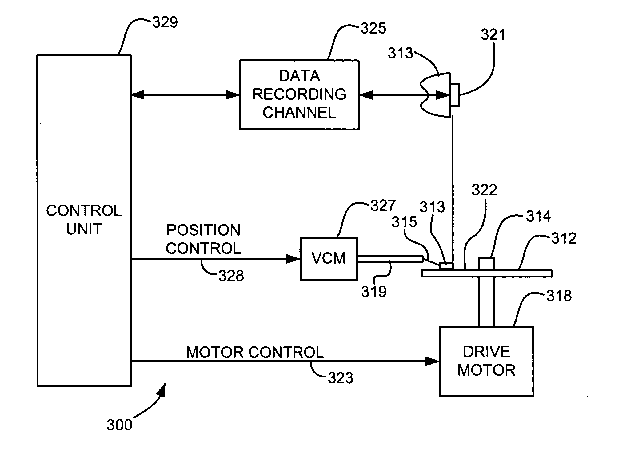
[0046] Referring now to FIG. 3, there is shown a disk drive 300 embodying the present invention. As shown in FIG. 3, at least one rotatable magnetic disk 312 is supported on a spindle 314 and rotated by a disk drive motor 318. The magnetic recording on each disk is in the form of an annular pattern of concentric data tracks (not shown) on the disk 312.

[0047] At least one slider 313 is positioned near the disk 312, each slider 313 supporting one or more magnetic read / write heads 321. More information regarding such heads 321 will be set forth hereinafter during reference to FIG. 4. As the disks rotate, slider 313 is moved radially in and out over disk surface 322 so that heads 321 may access differe...


PUM

PropertyMeasurementUnit
heightsaaaaaaaaaa
flying heightsaaaaaaaaaa

Abstract

A new structure for adjusting flying height using a magnetomechanical effect. A head includes a magnetomechanically active structure and a coil coupled to the magnetomechanically active structure, the magnetomechanically active structure responding to a magnetic field generated by the coil to expand and/or contract.

Description

FIELD OF THE INVENTION [0001] The present invention relates to magnetic recording heads having controlled protrusion for tuning fly heights thereof, and more particularly, this invention relates to incorporation of a material having high magnetostriction into a magnetic head for providing controlled protrusion of the head. BACKGROUND OF THE INVENTION [0002] In a disk drive, a magnetic recording head is made of read and write elements. The write element is used to record and erase data bits arranged in circular tracks on the disk while the read element plays back a recorded magnetic signal. The magnetic recording head is mounted on a slider which is connected to a suspension arm, the suspension arm urging the slider toward a magnetic storage disk. When the disk is rotated the slider flies above the surface of the disk on a cushion of air which is generated by the rotating disk. [0003] The read element is generally made of a small stripe of multilayer magnetic thin films which have ei...

Claims


Application Information

Patent Timeline
Patent Type & Authority Applications(United States)
IPC IPC(8): G11B5/60G11B21/02
CPCG11B5/6005G11B5/3136
Inventor NIKITIN, VLADIMIRGIDER, SAVASHSIAO, WEN-CHIEN
Owner HITACHI GLOBAL STORAGE TECH NETHERLANDS BV
Why Eureka
Try Eureka