Optical fiber cable and method of mid-span access thereof

a technology of optical fiber cable and mid-span access, applied in the direction of optics, fiber mechanical structure, instruments, etc., can solve the problems of proper protection measure and fiber exposed to the exterior, and achieve the effect of increasing transmission loss and preventing damag

Inactive Publication Date: 2011-01-06
THE FUJIKURA CABLE WORKS LTD
View PDF5 Cites 11 Cited by
  • Summary
  • Abstract
  • Description
  • Claims
  • Application Information

AI Technical Summary

Benefits of technology

[0005]Some circumstances cause damage to properties of the optical fibers. For example, as the slotted core is likely to move relative to the sheath, projection of the slotted core out of one end of the sheath may occur. The projection will lead to damage to the optical fibers at the projecting part. Fu

Problems solved by technology

As the fibers exposed to the exterior are susceptible to

Method used


Image

  • Optical fiber cable and method of mid-span access thereof
  • Optical fiber cable and method of mid-span access thereof
  • Optical fiber cable and method of mid-span access thereof

Examples


first embodiment

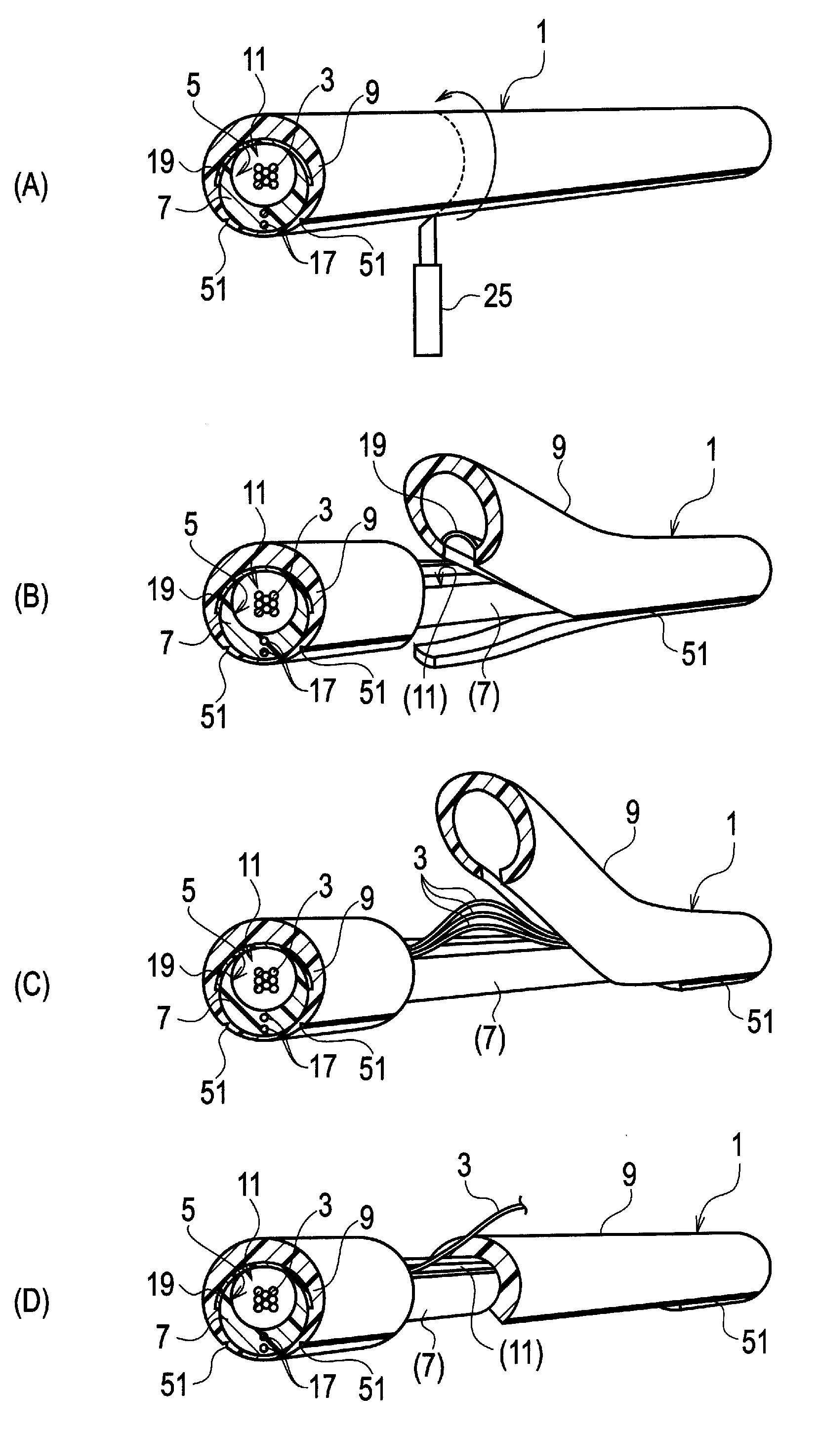
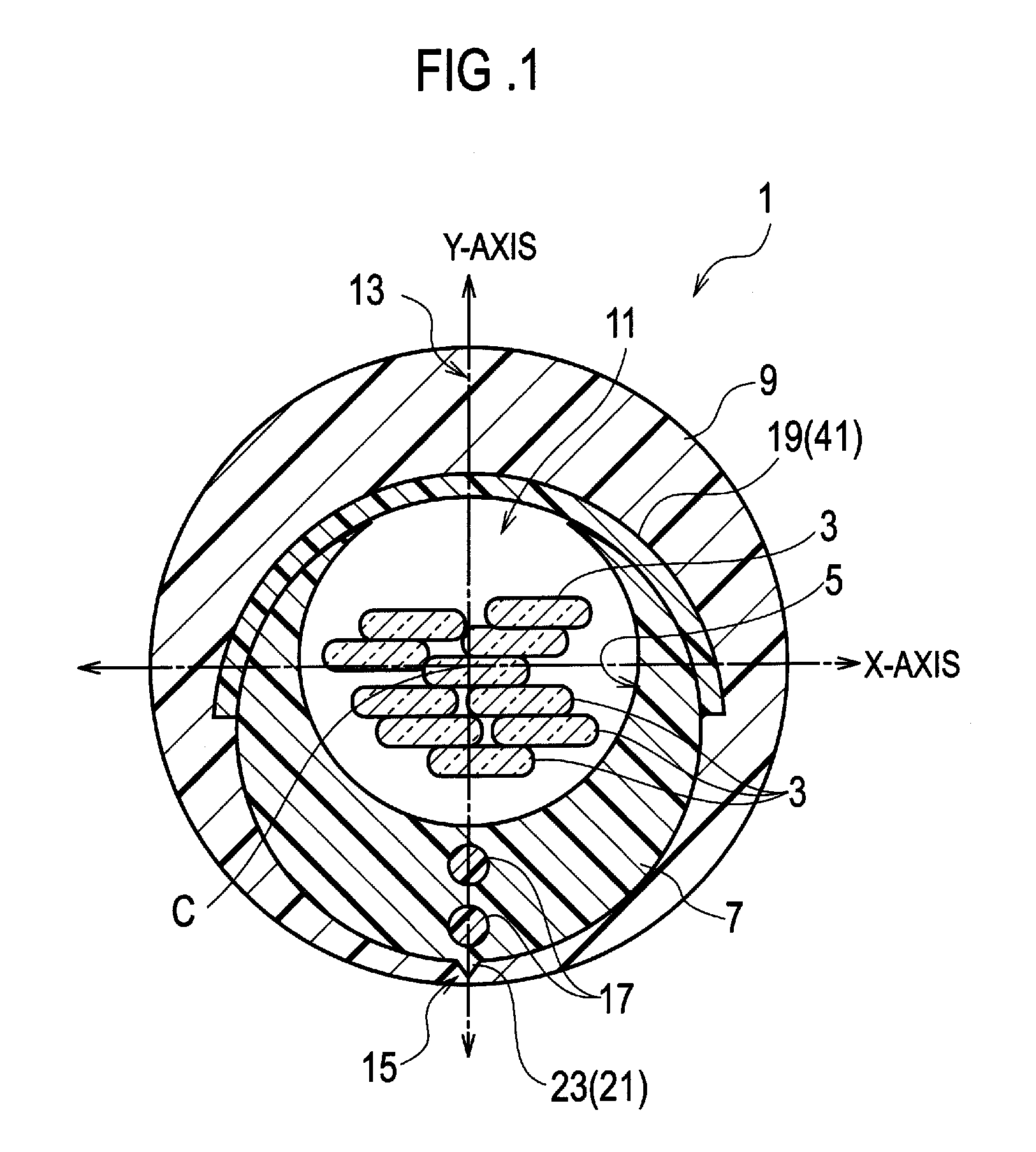
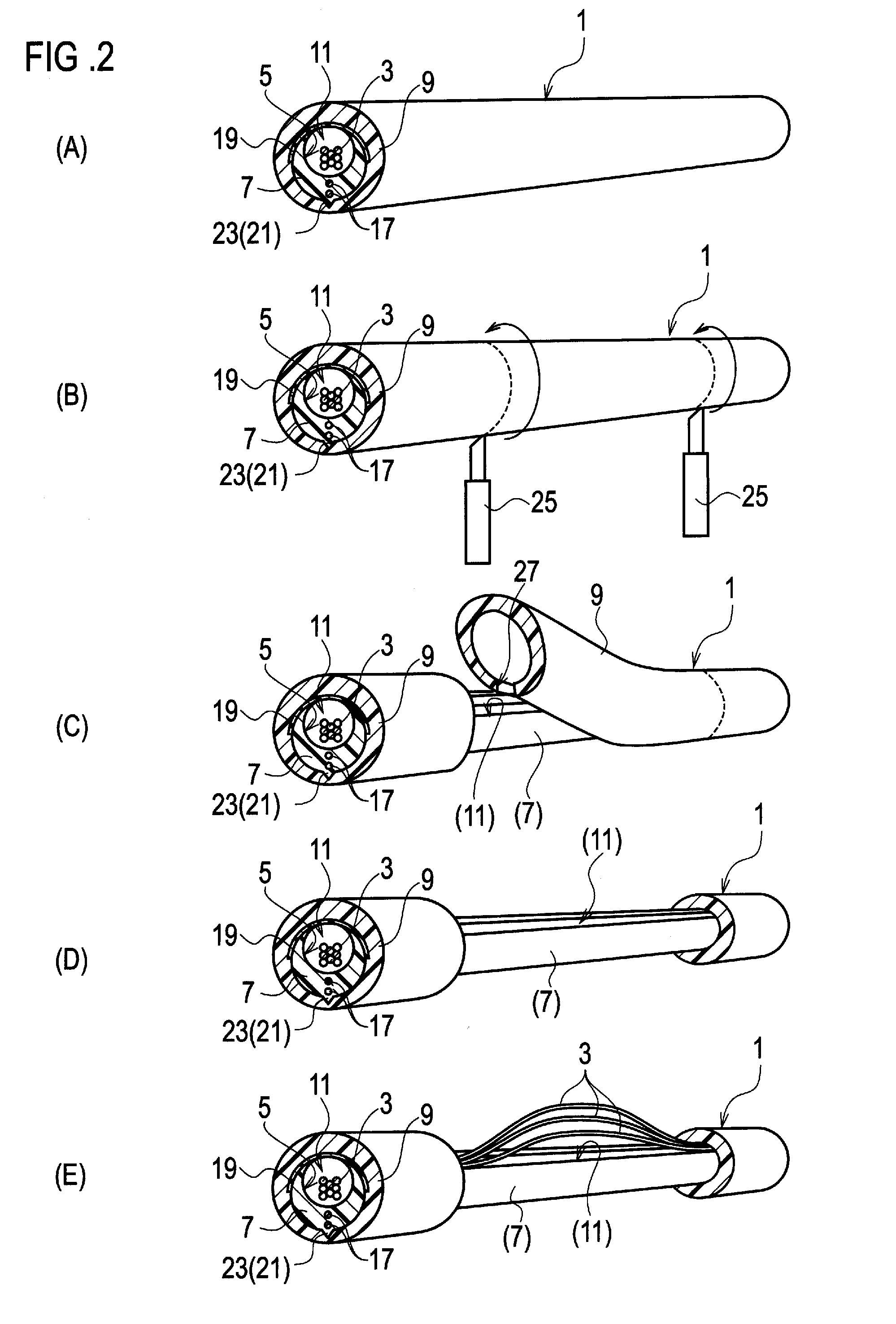
[0026]Referring to FIG. 1, an optical fiber cable 1 according to the present invention is comprised of optical fibers 3, a slotted core 7 having a groove 5 for housing the optical fibers 3, and a sheath 9 enclosing the slotted core 9 along with the optical fibers 3. Needless to say, all the fibers 3, the groove 5, the core 7, the sheath 9 and the slot 11 run in parallel with the central axis C of the optical fiber cable 1.

[0027]The slotted core 7 is further comprised of a slot 11 opened linearly along the slotted core 7 for enabling access to the interior of the groove 5. Therefore the slotted core 7 has a C-letter cross sectional shape. The wall of the slotted core 7 gradually becomes thicker toward the side opposite to the slot 11. The groove 5 is eccentric from the outer profile of the slotted core 7. When the center of the slot 11 and the side just opposite to the slot 11 are made aligned on the Y-axis, the eccentricity is also in a direction along the Y-axis.

[0028]The sheath 9 ...

second embodiment

[0057]Referring to FIG. 4 which illustrates a second embodiment, the slotted core 7 is in part given roughness in advance of bonding and the rough surface of the slotted core 7 is subject to thermal fusion bonding to form a bonding portion 23 with the sheath 9. The bonding portion 23 is composed of a thermal fusion bonding portion 31 produced by the thermal fusion bonding, where the slotted core 7 and the sheath 9 are fused together and thereby locally form a unitary body.

third embodiment

[0058]Alternatively, in a third embodiment, the slotted core 7 is in part heated up to a temperature sufficiently close to, or higher than, that of the sheath 9 in advance of bonding so as to cause softening of the slotted core 7, and then thermal fusion bonding is carried out.


PUM


Abstract

An optical fiber cable is comprised of: a slotted core (7) elongated along an axis of the optical fiber cable, the slotted core including a slot (11) running in parallel with the axis and a groove (5) accessible through the slot; one or more optical fibers (3) placed in the groove; a sheath (9) enclosing the slotted core and the optical fibers; a bonding portion (15) where the slotted core is bonded with the sheath; and two or more strength members (17) embedded in the slotted core, the strength member running in parallel with the axis, and being aligned on a plane including the axis.

Description

TECHNICAL FIELD[0001]Apparatuses consistent with the present invention relate to optical fiber cables enclosing fibers, in which enclosed fibers are easily accessible but prevented from damage, and a method of mid-span access of the optical fiber cables.BACKGROUND ART[0002]An optical fiber cable in some cases includes plural fibers for the purpose of increasing the capacity or the number of devices linking via the cable. These fibers may be enclosed with a slotted core and the slotted core along with the fibers may be further enclosed with a sheath.[0003]After being laid, some optical fiber cables are often subject to a work named “mid-span access” to make the enclosed optical fibers branch off. In the mid-span access work, the sheath and the core are cut and split to enable access to one or more of the enclosed fibers. As the fibers exposed to the exterior are susceptible to damage, any proper measure for protection may be required.[0004]Japanese Patent Unexamined Application Publi...

Claims


Application Information

Patent Timeline
IPC IPC(8): G02B6/44
CPCG02B6/4429G02B6/4495G02B6/4432G02B6/4431
Inventor OSATO, KENOKADA, NAOKITOMIKAWA, KOUJI
Owner THE FUJIKURA CABLE WORKS LTD
Why Eureka
Try Eureka