Control device for vehicle drive device

a technology of control device and drive device, which is applied in the direction of electric propulsion mounting, vehicle sub-unit features, transportation and packaging, etc., can solve the problems of deterioration in power performance, deterioration in fuel efficiency performance or deterioration in controllability of certain control in fluid transmission device or automatic transmission, and fuel efficiency performance degradation, so as to reduce the speed ratio of fluid transmission device and fuel efficiency. , the effect of fuel efficiency

Active Publication Date: 2014-10-16
TOYOTA JIDOSHA KK
View PDF1 Cites 10 Cited by
  • Summary
  • Abstract
  • Description
  • Claims
  • Application Information

AI Technical Summary

Benefits of technology

[0008]Consequently, since the operating point of the engine can be controlled without being constrained by a rotation speed of the output-side rotating element by adjusting the torque of the first electric motor, the engine can be driven at an operating point optimal for the fuel efficiency improvement, for example, and the vehicle fuel efficiency can be improved. Additionally, since the control of the operating point of the engine can be provided by adjusting the torque of the first electric motor, the speed ratio of the fluid transmission device can be reduced while giving/receiving electric power between the first electric motor and the second electric motor and, therefore, the transmission loss in the fluid transmission device is increased to increase the heat generation amount. Thus, a rise in the operating oil temperature can obviously be promoted, and the rise in the operating oil temperature can promote warm-up of an apparatus actuated by the operating oil. Since the adjustment of the torque of the first electric motor is performed by giving/receiving electric power between the first electric motor and the second electric motor, the loss of the fluid transmission device can be increased regardless of the charged capacity of the battery (electric storage device) etc. Therefore, the warm-up can be promoted in a wider range without being limited by the charged capacity of the electric storage device etc.
[0009]The second aspect of the invention provides the control device of a vehicle drive device recited in the first aspect of the invention, wherein the torque of the first electric motor is adjusted such that a sum of an engine torque and the torque of the first electric motor is balanced with an input-side load torque generated in the input-side rotating element depending on a speed ratio of the fluid transmission device, and wherein the input-side load torque is obtained based on an engine rotation speed indicated by a target engine operating point, and wherein the torque of the first electric motor is determined based on the input-side load torque and the engine torque indicated by the target engine operating point. Consequently, the torque of the first electric motor can easily be adjusted based on the characteristics of the fluid transmission device.
[0010]The third aspect of the invention provides the control device of a vehicle drive device recited in the second aspect of the invention, wherein a power running torque of the first electric motor is increased to raise an engine rotation speed relative to an engine

Problems solved by technology

If a temperature of operating oil (operating oil temperature) for actuating the fluid transmission device or an automatic transmission disposed on the subsequent stage of the fluid transmission device is lower, controllability may deteriorat

Method used


Image

  • Control device for vehicle drive device
  • Control device for vehicle drive device
  • Control device for vehicle drive device

Examples


example

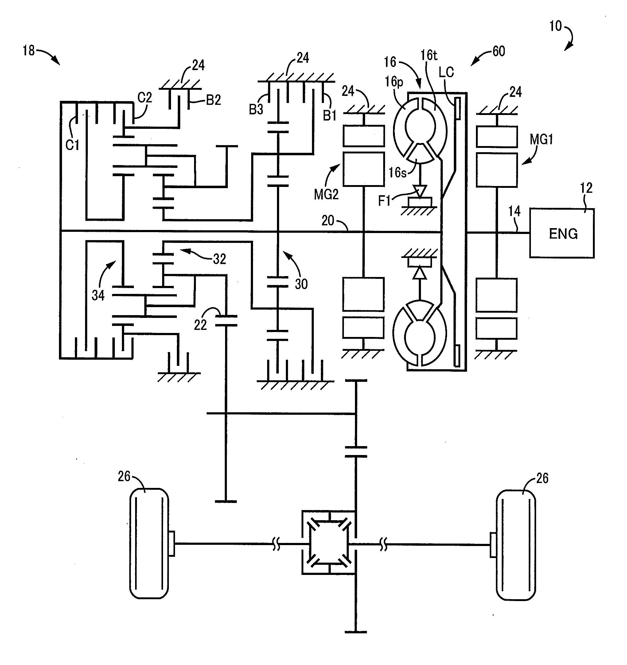
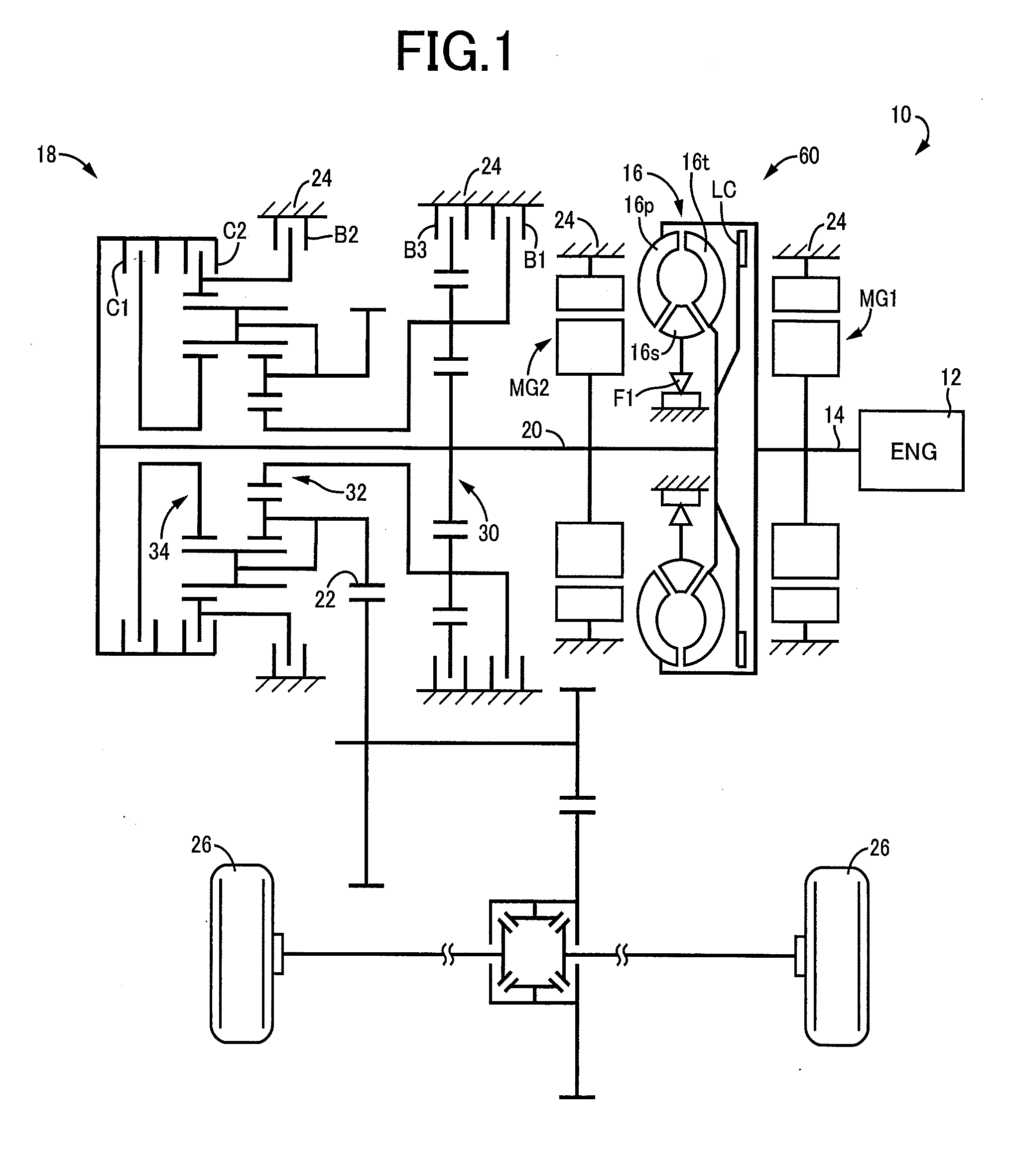
[0045]FIG. 1 is a schematic for explaining a configuration of a vehicle drive device 10 of an example of the present invention. In FIG. 1, the vehicle drive device 10 is preferably employed in FF (front-engine front-drive) type vehicles and includes an engine 12 that is an internal-combustion engine, a torque converter (fluid transmission device) 16 coupled to a crankshaft 14 of the engine 12, an automatic transmission 18 disposed between the torque converter 16 and drive wheels 26 and coupled to the output side of the torque converter 16, a first electric motor MG1 disposed between the engine 12 and the torque converter 16 and coupled to the crankshaft 14, and a second electric motor MG2 disposed between the torque converter 16 and the automatic transmission 18 and coupled to an input shaft 20 of the automatic transmission 18.

[0046]The torque converter 16 is a fluid transmission device including a pump impeller 16p acting as an input-side rotating element to which power from the en...


PUM


Abstract

A control device of a vehicle drive device includes a fluid transmission device having an input-side rotating element to which power from an engine is input and an output-side rotating element outputting power to drive wheels, a first electric motor directly or indirectly coupled to the input-side rotating element, and a second electric motor directly or indirectly coupled to the drive wheels, the control device of a vehicle drive device having an electric path through which power is electrically transmitted by giving/receiving electric power between the first electric motor and the second electric motor and a mechanical path through which power is mechanically transmitted via the fluid transmission device, the control device of a vehicle drive device being configured to control an operating point of the engine by adjusting a torque of the first electric motor, the torque of the first electric motor being adjusted such that a sum of an engine torque and the torque of the first electric motor is balanced with an input-side load torque generated in the input-side rotating element depending on a speed ratio of the fluid transmission device, the input-side load torque being obtained based on an engine rotation speed indicated by a target engine operating point, and the torque of the first electric motor being determined based on the input-side load torque and the engine torque indicated by the target engine operating point, and the control device of a vehicle drive device adjusting a torque of the first electric motor while giving/receiving electric power between the first electric motor and the second electric motor to reduce a speed ratio of the fluid transmission device when a temperature of operating oil for actuating the fluid transmission device is lower as compared to when the temperature is higher.

Description

TECHNICAL FIELD[0001]The present invention relates to a control device of a vehicle drive device including an engine, an electric motor, and a fluid transmission device such that the power of the engine can be transmitted through a plurality of transmission paths.BACKGROUND ART[0002]A vehicle drive device is well known that includes a fluid transmission device having an input-side rotating element to which power from an engine is input and an output-side rotating element outputting power to drive wheels. For example, this corresponds to a vehicle drive device described in Patent Document 1. Such a vehicle drive device has an engine rotation speed (corresponding to a rotation speed of the input-side rotating element of the fluid transmission device) passively determined depending on a vehicle speed (corresponding to a rotation speed of the output-side rotating element of the fluid transmission device), the characteristic of the fluid transmission device, and the engine output. Power ...

Claims


Application Information

Patent Timeline
IPC IPC(8): B60K1/02B60L50/16
CPCB60K1/02B60K6/442B60K6/485B60K6/547B60W10/023B60W10/08B60W30/194B60K2006/4825B60Y2400/426B60W2710/1072Y02T10/62Y02T10/72
Inventor TABATA, ATSUSHIIMAMURA, TATSUYAMATSUBARA, TOORU
Owner TOYOTA JIDOSHA KK
Why Eureka
Try Eureka