Apparatus and method for swaging needles

a needle and needle attachment technology, applied in the field of needle attachment apparatus and methods, can solve the problems of injuring the tissue, unnecessarily enlarge the hole in the tissue, and failure of the suture material,

Active Publication Date: 2010-10-19
ETHICON INC
View PDF82 Cites 23 Cited by
  • Summary
  • Abstract
  • Description
  • Claims
  • Application Information

AI Technical Summary

Problems solved by technology

Generally, suture material has some degree of deformability / malleability, but there are limits to same, which, when exceeded, lead to suture material failure.
Out of round conditions or sharp edges produced by swaging can increase the drag that the needle experiences when passing through the tissue being sutured, injure the tissue and / or unnecessarily enlarge the hole in the tissue made by the needle as it is passes through the tissue during use.
While this produces good results, the apparatus used is more complex and expensive than single hit swaging apparatus and the process takes longer.

Method used


Image

  • Apparatus and method for swaging needles
  • Apparatus and method for swaging needles
  • Apparatus and method for swaging needles

Examples


example 1

[0040]Given:[0041]Wire Dia Wd:=0.026[0042]Suture Dia Sd:=0.01255[0043]Hole Dia Hd:=0.0157[0044]Nib Radius NR:=0.003[0045]Suture Compression Ratio C:=10%; then[0046]Nib Spacing Ns:=0.012″[0047]Cb:=0.0098″[0048]CT:=0.0113″[0049]Ratio:=0.8686[0050]Ac:=27.36°

example 2

[0051]Given:[0052]Wire Dia Wd:=0.026″[0053]Suture Dia Sd:=0.01255″[0054]Hole Dia Hd:=0.0157″[0055]Nib Radius NR:=0.003″[0056]Suture Compression Ratio C:=20%; then[0057]Nib Spacing Ns:=0.012″[0058]Cb:=0.0076″[0059]CT:=0.0100″[0060]Ratio:=0.760[0061]Ac:=30.125°

example 3

[0062]Wire Dia Wd:=0.026[0063]Suture Dia Sd:=0.01255[0064]Hole Dia Hd:=0.0157[0065]Nib Radius NR:=0.003[0066]Suture Compression Ratio C:=26%; then[0067]Nib Spacing Ns:=0.012″[0068]Cb:=0.0063″[0069]CT:=0.0092″[0070]Ratio:=0.6804[0071]AC:=32.04°

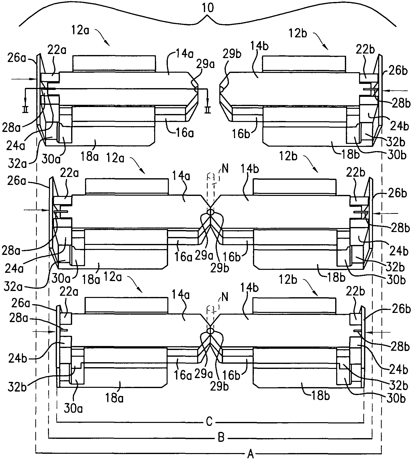
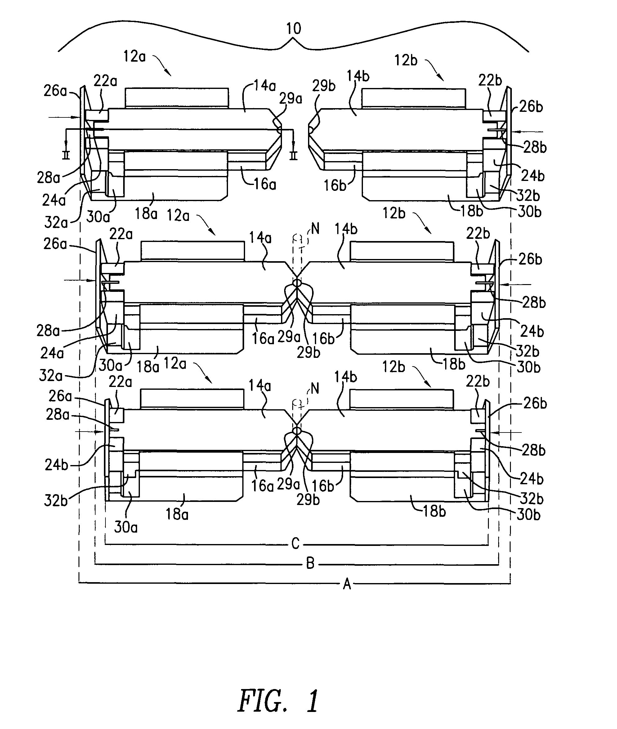
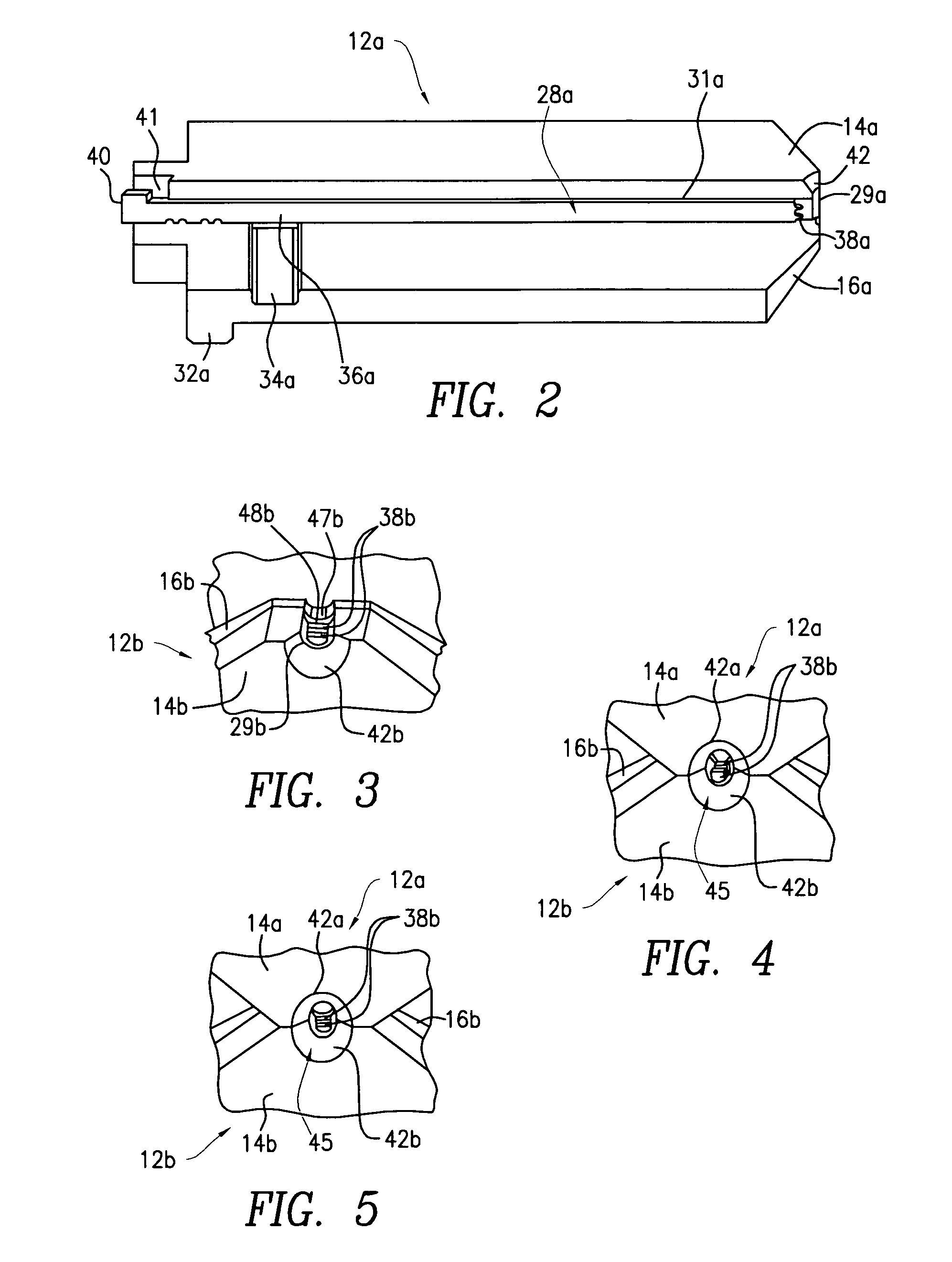
[0072]FIG. 20 shows another type of swage die 80 having a needle guide 82 and needle stop 84 similar to that shown in FIGS. 1-5, but held in a support 86 by a cap 88 retained to the support 86 by a pair of Allen bolts 89a, 89b or the like. The needle guide 82 and needle stop 84 are urged away from a ledge 93 of the support 86 by a pair of springs 90, 92, e.g., coil springs. The springs may be inserted into corresponding sockets 94, 96 to prevent them from slipping out of position on the ledge 93. Similar sockets or other spring retaining means (not shown) may be provided on the needle guide 82 and / or the needle stop 84 to retain the springs 90, 92.

[0073]FIG. 21 shows the swage die 80 of FIG. 20 held in a needle holder 98.

[0074]The present inven...


PUM

PropertyMeasurementUnit
diameteraaaaaaaaaa
diameteraaaaaaaaaa
sizeaaaaaaaaaa

Abstract

A method and apparatus for making armed sutures has a pair of opposed die assemblies that may be driven by actuating surfaces of a swaging machine to hold and swage a needle on a suture. The dies grip and confine the needle in the area of the suture receptacle. A pair of opposed swaging elements with offset stakes insert through passageways in the dies and impinge on the captured needle making a plurality of indentations in the needle barrel and gripping the suture in the suture receptacle. The indentations are offset and aligned generally in alternating peak-to-valley relationship, causing the suture receptacle and the contained suture to assume a serpentine configuration. The stakes and the resulting indentations can be dimensioned to result in a converging suture receptacle, which exhibits increasing shear force being exerted on the suture with increasing depth into the suture receptacle. The apparatus and method permit reliable suture-needle attachment over a larger range of tolerances, such that a single die setup can be used on a plurality of needle and suture materials. The resulting product exhibits a serpentine suture / needle attachment interface with reliable attachment and smooth outer dimensions.

Description

FIELD OF THE INVENTION[0001]The present invention relates to apparatus and methods for attaching needles to sutures, such as for making armed sutures for surgical application, and more particularly, to methods of attaching surgical needles to sutures using a swaging process.BACKGROUND OF THE INVENTION[0002]Various methods for swaging needles to sutures are known. Given a needle of a desired gauge, composition and shape, a hole is formed in one end. The hole extends axially into the needle to constitute a suture receptacle and may be formed by mechanical or laser drilling. The term “needle” as used herein is intended to refer to a surgical needle, such that the term “needle” is intended to be a short form of the term “surgical needle” and is synonymous therewith. Typically, the end of the needle having the suture receptacle could be generally described as being in the form of a hollow cylinder, the diameter of the interior hollow of the cylinder being greater than the outside diamete...

Claims


Application Information

Patent Timeline
Patent Type & Authority Patents(United States)
IPC IPC(8): B21J7/16
CPCA61B17/06004B21G1/006B21J9/06A61B2017/00526Y10T29/49826Y10T29/53709Y10T29/53791Y10T29/53787
Inventor PRICE, JOHN J.STAMETZ, JERRY W.BARSCH, KENNETH R.
Owner ETHICON INC
Why Eureka
Try Eureka