Compact log splitter

a log splitter and compact technology, applied in the field of log splitters, can solve the problems of inconvenient use of horizontal splitters, inefficiency in the splitting process, and the required strength of log splitter components, and achieve the effect of minimizing the size of the splitter

Active Publication Date: 2010-10-19
NORTHERN TOOL & EQUIP
View PDF17 Cites 16 Cited by
  • Summary
  • Abstract
  • Description
  • Claims
  • Application Information

AI Technical Summary

Benefits of technology

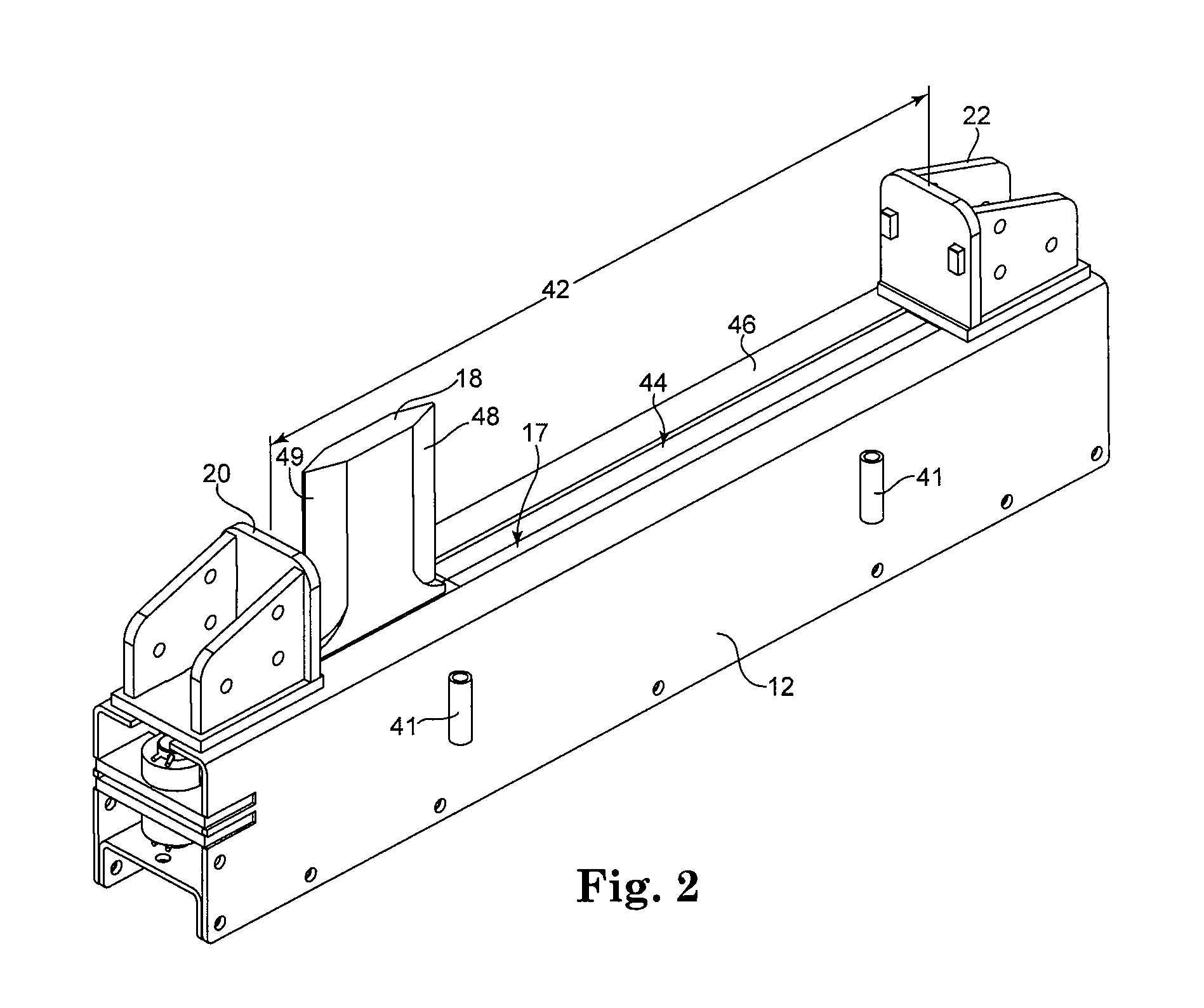
[0009]Due to the nested structure of the splitting device, the size of the splitter is minimized because the support structure does not have to be designed with a longitudinal length that is sufficient to account for both the longitudinal length of the drive mechanism and the longitudinal length of travel of the splitting wedge.

Problems solved by technology

However, as the amount of hydraulic force supplied by the hydraulic cylinder increases, so does the required strength of the log splitter components.
However, horizontal splitters can be inconvenient to use when splitting large, heavy pieces of wood.
This creates safety hazards to operators as well as inefficiencies in the splitting process.
Current horizontal-type log splitter designs are often large and bulky, making them difficult to both transport and store when not in use.
The length of the splitting zone and the length of the cylinder, when added together, require the splitter to be quite long, thus being difficult to handle.
In addition, post-manufacture shipment of these log splitters to retail locations and the like is inconvenient and expensive due to their size and shape.
For example, most current horizontal-type log splitters are too large to be shipped on a standard size pallet.
As mentioned above, one common design element that has made these log splitters large and bulky is the coupling of the splitting wedge or pusher in series with a hydraulic cylinder.

Method used


Image

  • Compact log splitter
  • Compact log splitter
  • Compact log splitter

Examples


Embodiment Construction

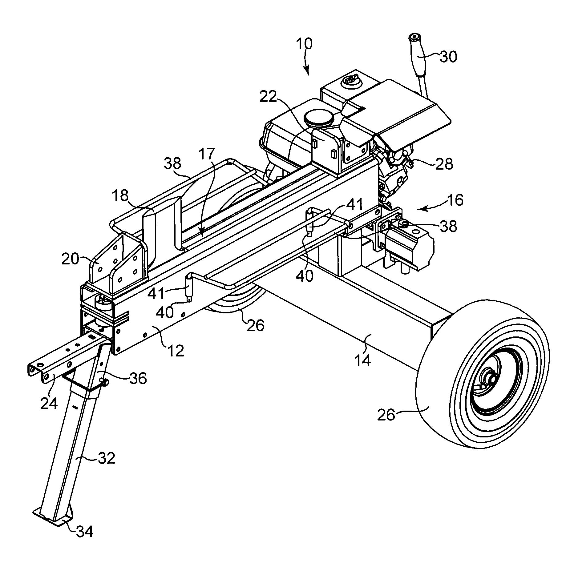
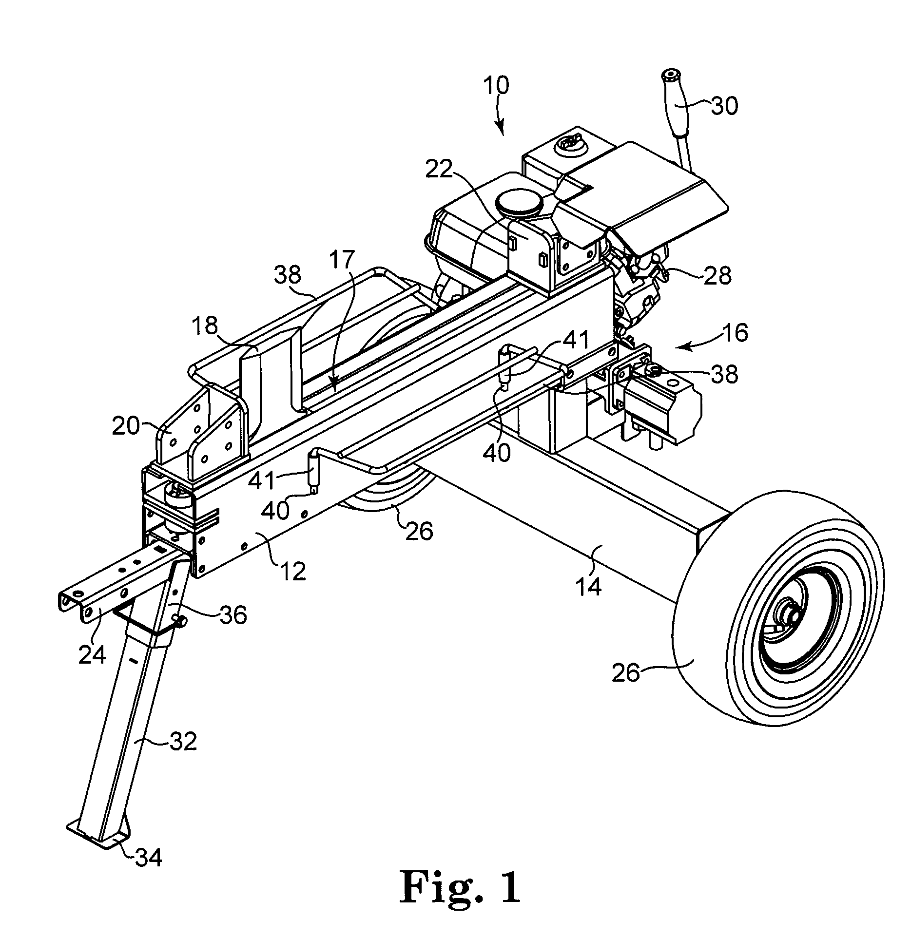
[0017]FIG. 1 is a perspective view of a log splitter 10 in accordance with the present invention. As shown in FIG. 1, log splitter 10 includes support structure 12, wheel base 14, drive system 16 connected to support framework 12 and wheel base 14, a splitting device 17 having a splitting wedge 18 operably coupled to drive system 16, first stop member 20, and second stop member 22. Log splitter 10 shown in FIG. 1 is a trailer-type log splitter having hitch 24 and wheels 26 in order to couple log splitter 10 to a transport vehicle, allowing the splitter to be moved from location to location. Alternatively, those skilled in the art will appreciate that log splitter 10 may be stationary, variable in size and / or designed to be disassembled into smaller components for transportation, storage, etc., and reassembled when necessary for use.

[0018]Drive system 16 includes pump and motor assembly 28, control handle 30, a control valve (not shown), and a hydraulic cylinder or drive mechanism (n...


PUM


Abstract

A log splitter comprises a support structure having a first end, a second end, and an open center portion defined therebetweeen, a splitting device slidably coupled to the support structure, and a drive mechanism for driving movement of the splitting device through a splitting zone. The splitting device comprises an elongate beam having an outer surface, a first end, a second end, and an open center portion between the first end and the second end, and a splitting wedge coupled to the outer surface of the elongate beam and having at least one splitting surface formed thereon. The elongate beam is disposed within the open center portion of the support structure. The drive mechanism is disposed within the open center portion of the elongate beam, and is coupled on a first end to the first end of the support structure and on a second end to the second end of the elongate beam.

Description

BACKGROUND OF THE INVENTION[0001]The present invention relates in general to a log splitter. More particularly, the present invention relates to a compact log splitter having a splitting wedge coupled to a beam, where the beam has a drive mechanism disposed therein.[0002]Log splitting devices have been in use for decades. Conventional log splitters typically include a stationary support frame configured to support a hydraulic cylinder and a cooperating splitting wedge. Generally speaking, splitting of wood occurs by causing the splitting wedge to be forced through the wood, using the force of the hydraulic cylinder. In a fixed wedge version, the splitting wedge is fixed to the supporting frame, and the log is forced into the splitting wedge. In use, a log is placed in the appropriate position and is forcibly pushed against the stationary splitting wedge by the force created when the hydraulic cylinder is extended. Obviously, this requires movement or sliding of the log in order to c...

Claims


Application Information

Patent Timeline
Patent Type & Authority Patents(United States)
IPC IPC(8): B27L7/00B27L7/02
CPCB27L7/00
Inventor BABCOCK, STEPHEN EMERSON
Owner NORTHERN TOOL & EQUIP
Why Eureka
Try Eureka