Leaf catcher

a technology of leaf catcher and catcher, which is applied in the field of leaf catcher, can solve the problems of reducing the performance unable to teach features, and unable to meet the requirements of the above device, so as to achieve the effect of convenient setup and removal

Inactive Publication Date: 2010-10-19
CAMPBELL NICKIE S +2
View PDF30 Cites 32 Cited by
  • Summary
  • Abstract
  • Description
  • Claims
  • Application Information

AI Technical Summary

Benefits of technology

[0005]It is desirable to provide a collapsible device for efficiently funneling objects, such as leaves, into a bag. The device preferably includes a plurality of panels defining a passageway having an entrance and an exit. A support structure is provided that engages at least one of said plurality of panels defining said passageway. A first forwardly extending arm and a second forwardly extending arm are also preferably constructed of a plurality of panels that are affixed to the panels that define the passageway. The forwardly extending arms define an intake area adjacent said entrance to passageway. Inside surfaces of the first and second forwardly extending arms, which are adjacent to the intake area, are each substantially recessed at predetermined angles about a horizontal axis and define an inwardly pointed apex. Preferably, leaves or other objects are directed into the intake area with a leaf blower. The unique shape of the forwardly extending arms and associated panels that define the intake area result in advantageous airflow patterns that smoothly direct objects into the passageway.
[0006]A bag having a plurality of openings therein, e.g. a mesh bag, is removably affixed adjacent to the exit of the passageway. The bag is provided to collect objects passing through the passageway and to allow air to escape through openings in said bag. The plurality of panels that define the passageway preferably includes an upwardly angled lower panel configured such that the entrance to the passageway is larger than the exit of the passageway. The upwardly angled lower panel directs debris to an upper portion of the rear of the bag. Once openings in the rear of the bag are covered by debris, a circulation pattern develops wherein debris flows from back to front along a bottom of the bag before re-entering the high velocity airstream passing through the passageway. The result is a tendency not to clog the passageway with debris.
[0007]The plurality of panels that make up the leaf catcher are preferably collapsible into a substantially flat configuration for ease of transport and storage. Further, the construction of the leaf catcher enables easy set up and take down when manipulating the panels from a folded to a operational configuration and vice versa.

Problems solved by technology

The collection of leaves and other debris from a yard or other land is tedious and time consuming.
None of the above patents, however, teach features for enhancing the airflow through a passageway and into a collection bag.
Instead, when used with a leaf blower that expels high velocity air flows for directing leaves and other debris, performance of the above devices may be diminished due to turbulent airflow, which tends to allow leaves to escape the device rather than direct the leaves into the collection receptacle.
Additionally, many of the above devices are not collapsible.
Consequently, such devices are inconvenient for a typical homeowner, whose storage space may be limited.

Method used


Image

  • Leaf catcher
  • Leaf catcher
  • Leaf catcher

Examples


Embodiment Construction

[0017]Before explaining the present invention in detail, it is important to understand that the invention is not limited in its application to the details of the embodiments and steps described herein. The invention is capable of other embodiments and of being practiced or carried out in a variety of ways. It is to be understood that the phraseology and terminology employed herein is for the purpose of description and not of limitation.

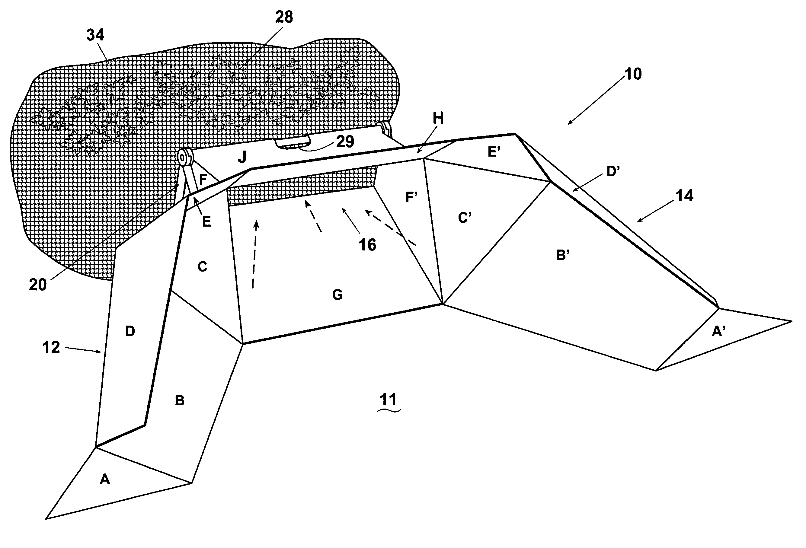
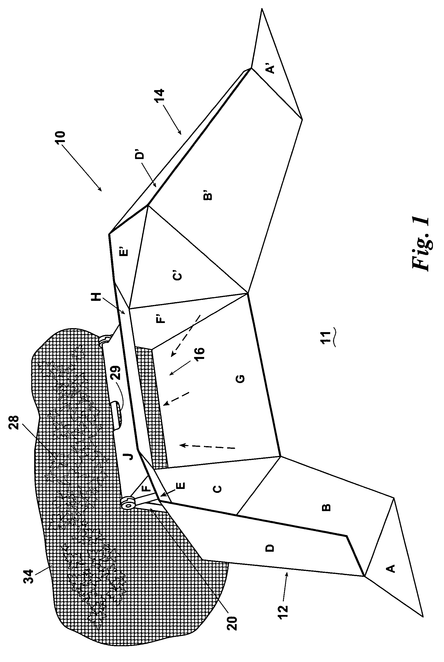
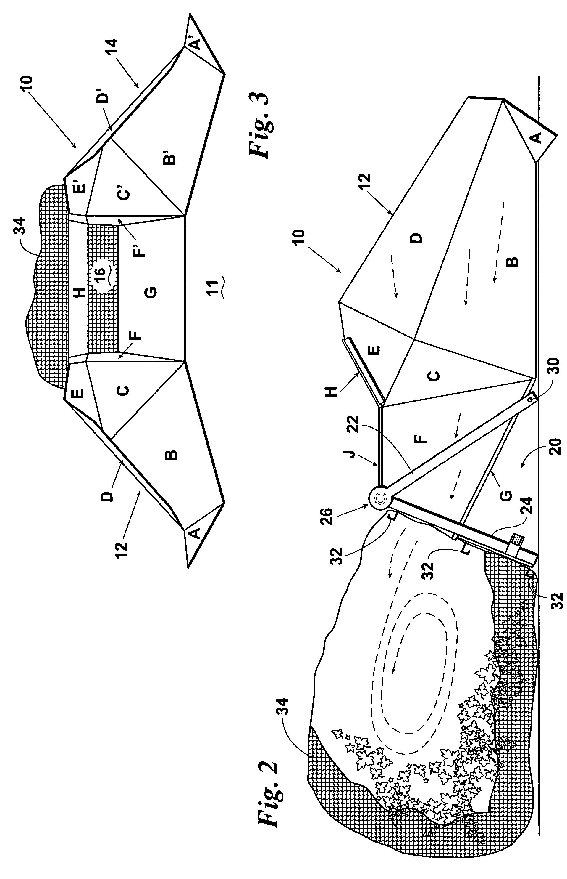
[0018]Referring now to FIGS. 1-4, the leaf catcher device of the invention is indicated generally by numeral 10. Leaf catcher 10 is comprised of a plurality of panels foldably connected to one another that are labeled herein as panels A-K. Panels A-K may be connected via “living hinges”, i.e. seams formed in plastic panels or by other means. As will be discussed in greater detail below, certain panels are removably affixed to one another, e.g., by Velcro®, snaps, or other means. Preferably, panels A-K may be folded in a flat configuration for ease of ...


PUM

PropertyMeasurementUnit
angleaaaaaaaaaa
areaaaaaaaaaaa
timeaaaaaaaaaa

Abstract

A device for funneling leaves into a bag, preferably used in conjunction with a leaf blower. The device includes a plurality of panels that define a passageway and two forwardly extending arms that define an intake area adjacent an entrance to the passageway. A bag is removably affixed adjacent to the exit of the passageway for receiving leaves and other objects blown therethrough. A ramp in the passageway induces circulating airflow in the bag. Additionally, the arms induce a corkscrew airflow and facilitate improved performance in directing objects through the passageway. The plurality of panels that make up the leaf catcher are preferably collapsible into a substantially flat configuration for ease of transport and storage. Further, the construction of the leaf catcher enables easy set up and take down when manipulating the panels from a folded to a operational configuration and vice versa.

Description

FIELD OF THE INVENTION[0001]This invention relates generally to a device for funneling objects, such as leaves, into a bag. More particularly, the invention relates to a collapsible device to assist a user in bagging leaves in a quick and efficient manner.BACKGROUND OF THE INVENTION[0002]The collection of leaves and other debris from a yard or other land is tedious and time consuming. Various methods are typically employed to gather the leaves in a manageable area for transferring the leaves into a bag or waste can.[0003]Numerous devices have been proposed for the collection of trash, leaves and other refuse. Some of the proposed devices employ a scoop or receiving section coupled to a bag or collection member. Examples of these types of devices include U.S. Pat. No. 5,107,666 to Rahtican for “Lawn Scoop”; U.S. Pat. No. 5,031,277 to Coker for “Debris Collecting and Bagging Apparatus”; U.S. Pat. No. D309,966 to Bishop for “Trash Bag Funnel”; U.S. Pat. No. D361,185 to Seiler et al., f...

Claims


Application Information

Patent Timeline
Patent Type & Authority Patents(United States)
IPC IPC(8): B65B67/04
CPCB65B67/04B65B67/1205B65B67/1238B65F1/1415B65F2240/138
Inventor CAMPBELL, NICKIE S.GORE, BOBBIE L.GORE, CAROLYN S.
Owner CAMPBELL NICKIE S
Why Eureka
Try Eureka