Air flow direction in a temperature controlled railroad freight car

a technology of temperature control and air flow direction, which is applied in the direction of windows, railway bodies, axle-box lubrication, etc., can solve the problems of limiting the weight of cargo that could be carried, becoming increasingly difficult to ensure the air flow direction of the railroad freight car, and plenums vulnerable to damag

Active Publication Date: 2010-06-29
THE STATE OF OREGON ACTING BY & THROUGH THE OREGON STATE BOARD OF HIGHER EDUCATION ON BEHALF OF OREGON STATE UNIV +1
View PDF8 Cites 4 Cited by
  • Summary
  • Abstract
  • Description
  • Claims
  • Application Information

AI Technical Summary

Benefits of technology

[0009]In particular, in one preferred embodiment of the present invention an air outlet port from a refrigeration unit extends through an opening in an end wall of a railroad freight car body at a distance beneath a ceiling height and is interconnected with an inflow end of an upper plenum extending closely along the ceiling toward an opposite end wall of the car body. A diverter extends slopingly upward, from a location near a lower side of the air outlet port of the refrigeration unit, into the inflow end of the plenum, smoothly directing a flow of air from the outlet port of the refrigeration unit into the inflow end of the upper plenum. The diverter preferably includes an upper shoulder located at the inflow end of the upper plenum, defining a most constricted part of a path for the flow of air from the refrigeration unit, and an inner margin portion of the diverter extends away from the shoulder at a gently sloping angle, allowing the flow of air to expand slightly as it enters into the inflow end of the plenum.
[0010]In a preferred embodiment of the invention, an upper deflector is also included and provides a smoothly curved concave surface defining part of the path for the flow of air. The upper deflector extends from an end wall of the car, adjacent the inlet opening, to an upper interior surface of the upper plenum, and also contributes to smooth flow of air from the refrigeration unit into the plenum.
[0011]Smooth flow of air from the refrigeration unit into the upper plenum, combined with a smooth substantially unobstructed interior shape of the upper plenum, contributes to continued smooth flow of air throughout the upper plenum over the length of the temperature-controlled car, even in a car considerably longer than previously known refrigerated cars.

Problems solved by technology

This downward projection has also made the plenum vulnerable to damage from lift trucks moving cargo within such cars.
As railroad car sizes have increased it has become increasingly difficult to ensure even distribution of air throughout a railroad freight car, as needed in order to avoid uneven cooling that could damage parts of a sensitive cargo.
Another factor in the design of such railcars is the need to avoid excessive car weight, which would limit the weight of cargo that could be carried and add to the cost of fuel used in hauling the car.

Method used


Image

  • Air flow direction in a temperature controlled railroad freight car
  • Air flow direction in a temperature controlled railroad freight car
  • Air flow direction in a temperature controlled railroad freight car

Examples


Embodiment Construction

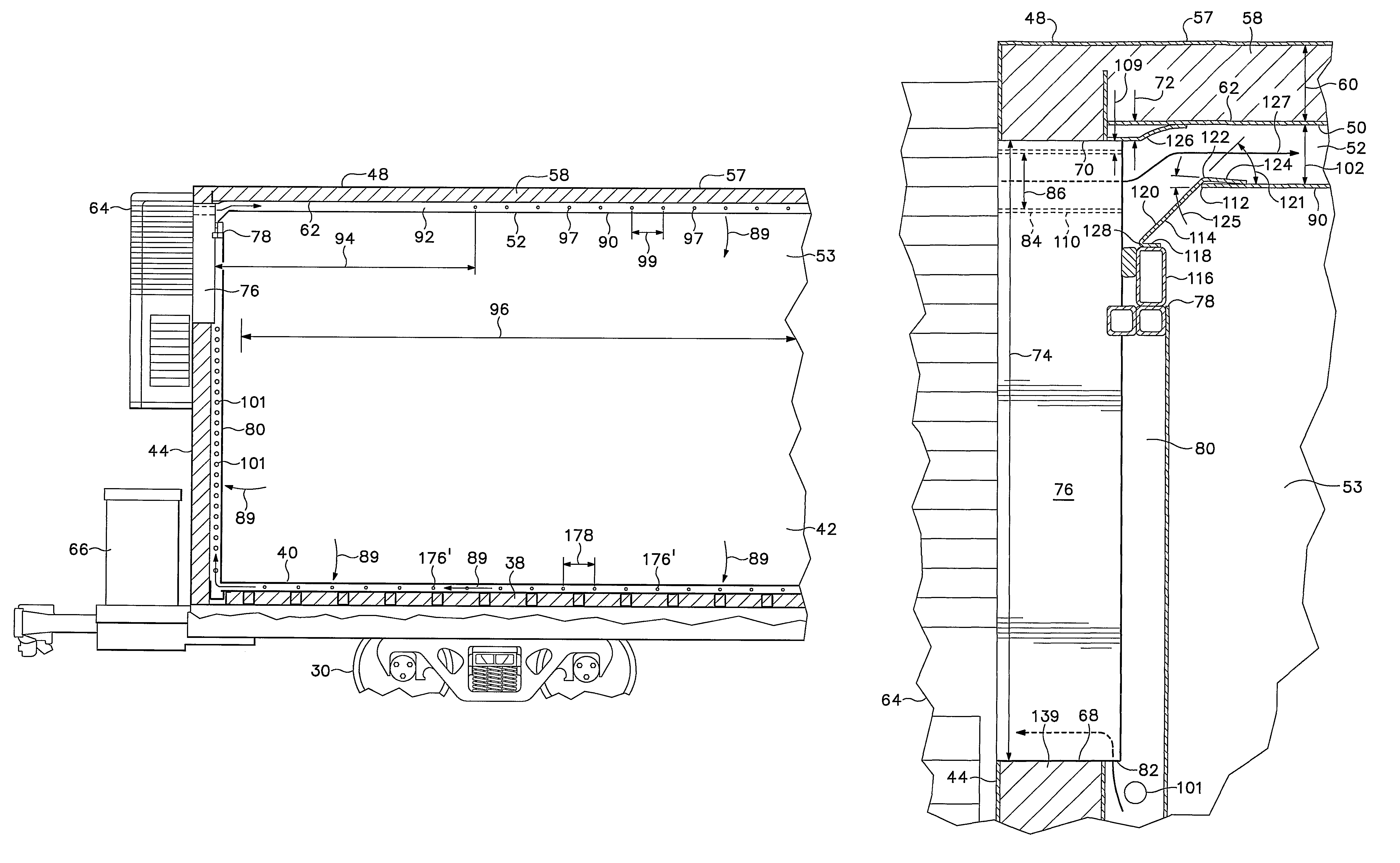
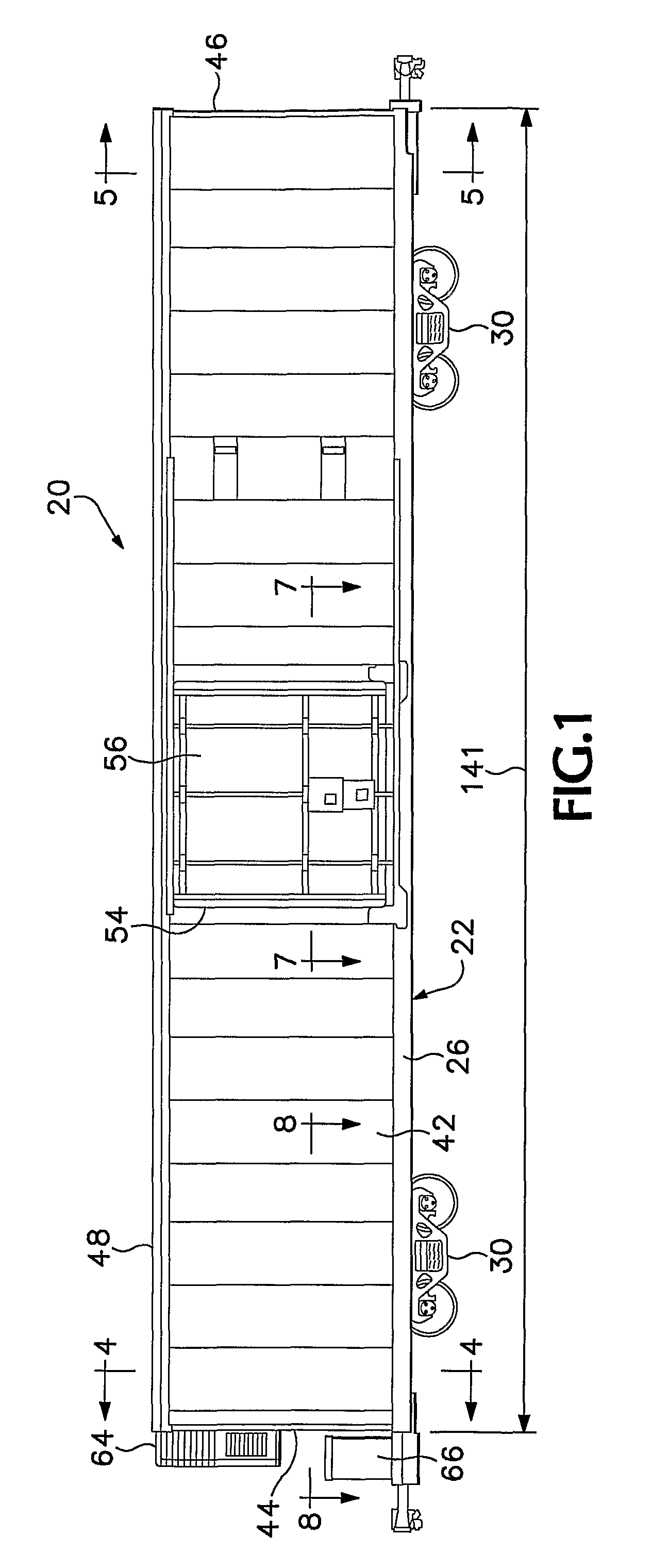
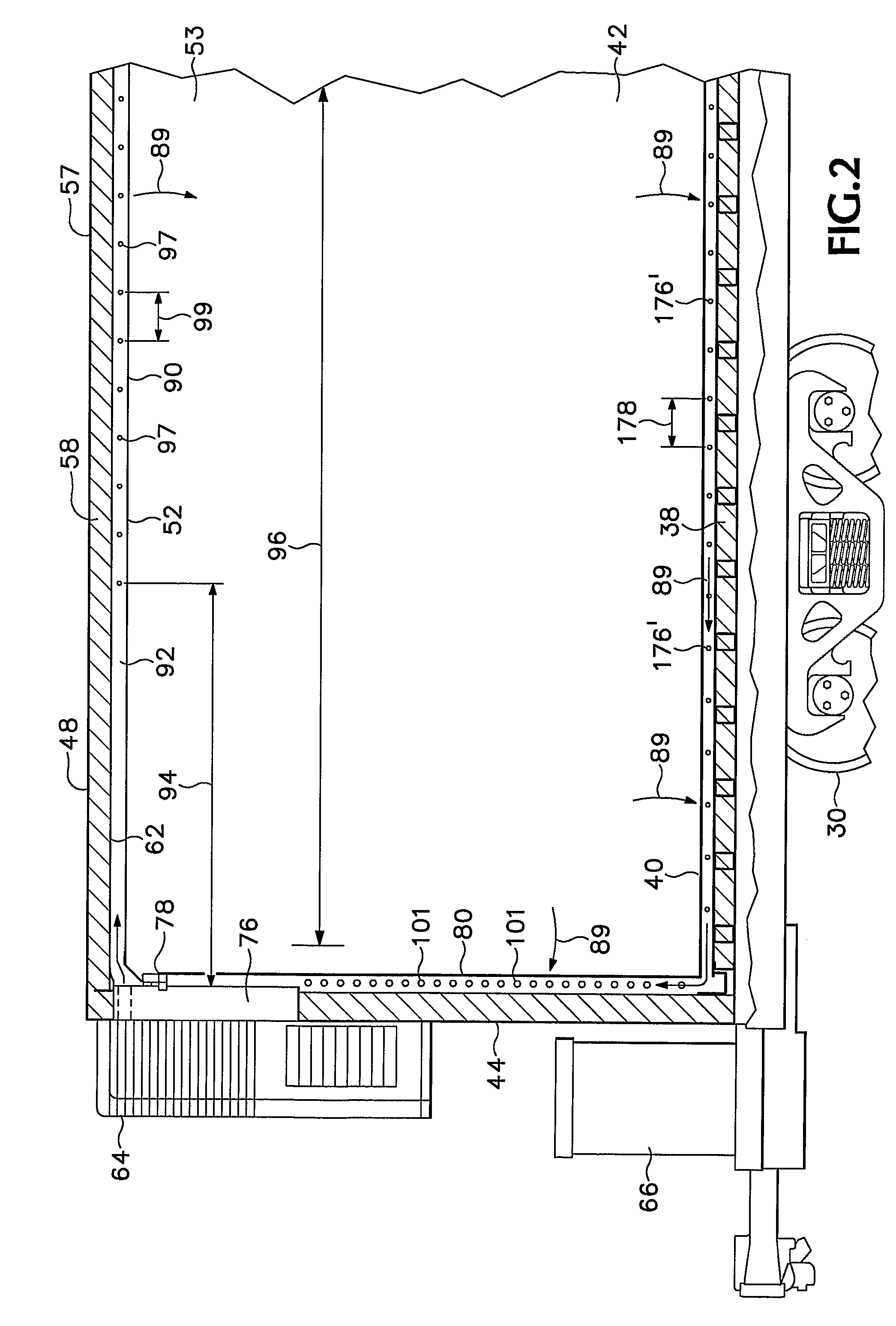
[0027]Referring now to FIGS. 1-8 of the drawings which form a part of the disclosure herein, a temperature-controlled railroad freight car 20 has an underframe structure 22 which may include a center sill 24, a pair of side sills 26, and a pair of body bolsters 28 each supported by a wheeled truck 30. Cross-bearers 32 extend from the center sill to each of the side sills 26, and crossties 34, of lighter construction, extend similarly at spaced-apart locations between those of the body bolsters 28 and cross-bearers 32. Longitudinal stringers 36 are spaced apart between the side sills 26 and center sill 24 and are carried by the bolsters 28, cross-bearers 32 and crossties 34, assisting in supporting a subfloor 38 and a floor 40 that rests on the subfloor 38. An end sill 41 is located at each end of the car body, interconnecting the opposite side sills 26 that extend the entire length of the car between the end sills.

[0028]Side walls 42 and end walls 44 and 46 are supported by the unde...


PUM


Abstract

An air flow conduit (98) and a related plenum (80) for distributing conditioned air from a refrigeration and heating unit (64) on an end (44) of a railroad freight car (20) into a cargo space (53) within the car (20). A deflector directs a flow of air upward into an inlet end of the plenum (80) and allows the flow to expand gradually within the plenum, smoothing the flow of air within the plenum so that it continues effectively at sufficient rates over the length of the car (20).

Description

BACKGROUND OF THE INVENTION[0001]The present application relates to temperature controlled railroad freight cars, and particularly to railroad freight car body structures incorporating air duct arrangements for circulation of air from a refrigeration or heating unit to various locations within a body of such a car while maximizing available cargo space.[0002]Temperature controlled railroad boxcars are well known, and have long used mechanical refrigeration and heating units mounted on an end wall, primarily to deliver chilled air to the interior of the car. For simplicity, the term refrigeration unit will be used herein to refer to refrigeration units, heating units, or units capable of both heating and cooling. Air from a refrigeration unit is typically forced into one end of an upper plenum extending longitudinally overhead, near the roof of the car, to deliver the conditioned air throughout the car to maintain a desired temperature throughout the cargo space in the car body. Such...

Claims


Application Information

Patent Timeline
Patent Type & Authority Patents(United States)
IPC IPC(8): B61D17/00B61D17/08B61D17/10B61D17/18
CPCB61D17/08B61D17/18B61D17/10
Inventor BECKER, BRUCE D.PENCE, DEBORAH V.
Owner THE STATE OF OREGON ACTING BY & THROUGH THE OREGON STATE BOARD OF HIGHER EDUCATION ON BEHALF OF OREGON STATE UNIV
Why Eureka
Try Eureka