Wind sail receptor

a wind sail and receptor technology, applied in the field of wind sail receptors, can solve the problems of lack of efficiency of wind mill blade configuration, heavy blades, and high construction and maintenance costs, and achieve the effects of less maintenance requirements, less and efficient conversion of wind or water flow energy into blade turning

Inactive Publication Date: 2007-12-18
WIND SAIL RECEPTOR
View PDF17 Cites 4 Cited by
  • Summary
  • Abstract
  • Description
  • Claims
  • Application Information

AI Technical Summary

Benefits of technology

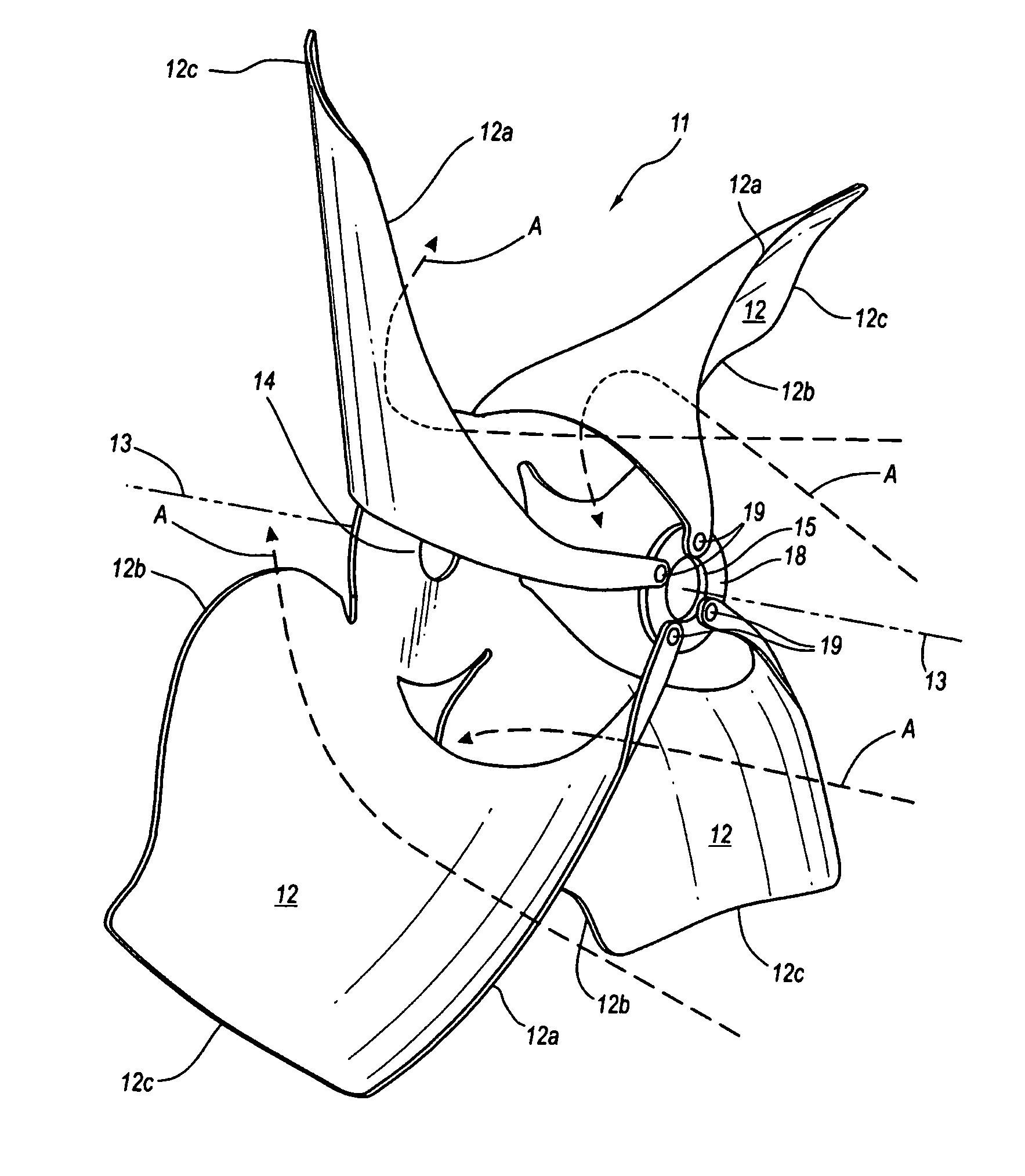
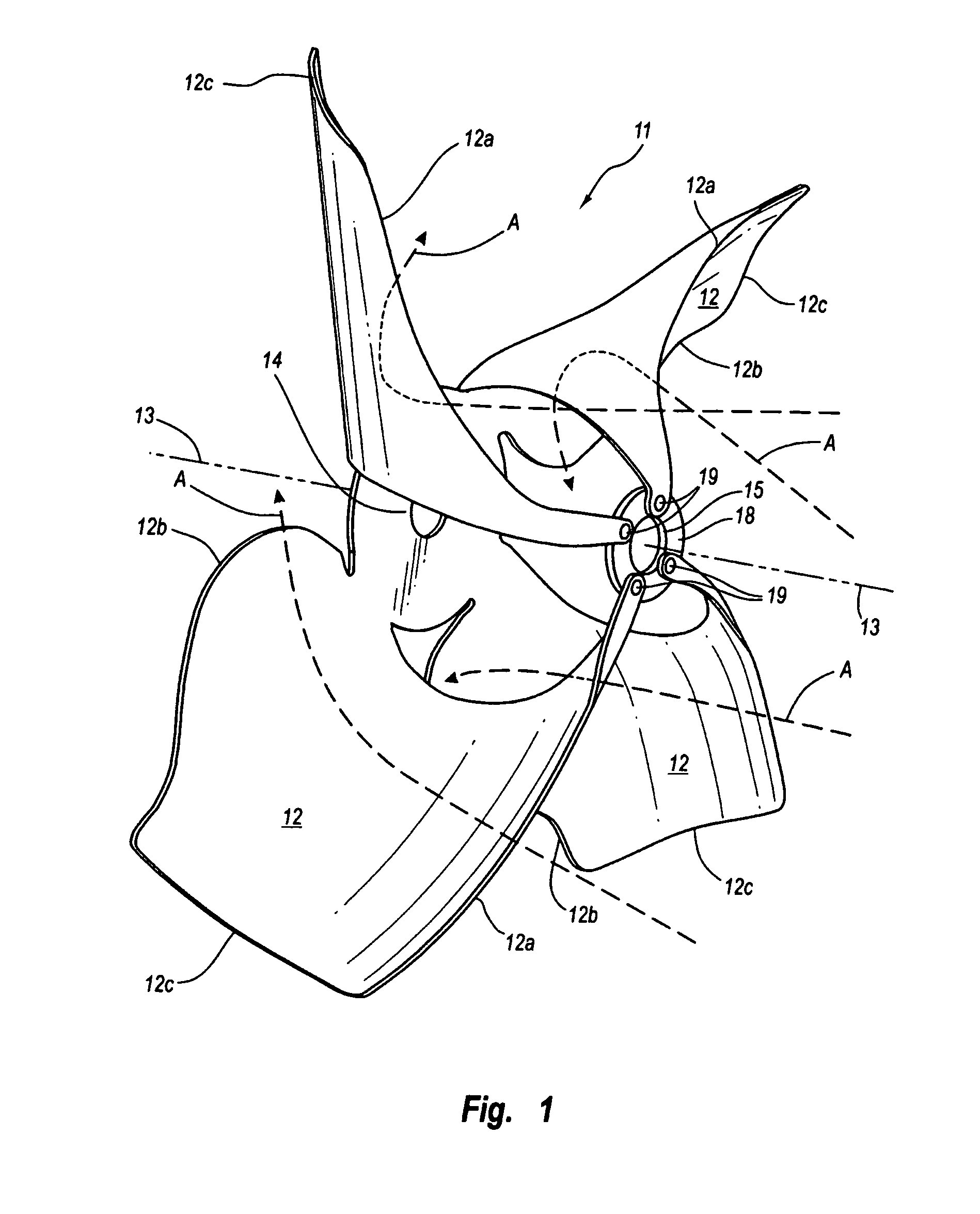
[0008]Another object of the present invention to provide a wind sail receptor were the individual blades are each curved from a leading to trailing edge to perform a function like that of a sail, like that of a head sail or jib of a sailing ship, and which blades are equally spaced from one another around a forward disk to where a flow of air passing across each blade leading edge acts around the curve of the blade to efficiently convert wind energy into blade rotation and turn an axle or shaft extending from the trailing face of a rear hub, turning a power generation device.
[0009]Another object of the present invention is to provide a wind sail receptor where a trailing edge of each blade has an half round section proximate to a blade hub, that translates into a flat outer section that extends to the blade end, and is to provide a flow path for a wind traveling around the blade curved surface to discourage generation of turbulence in the flow at the blade trailing edge.
[0010]Still another object of the present invention is to provide a novel design of wind sail receptor blades that, by their construction from a light gauge material, will respond to an increase in wing speed by becoming more rigid making each blade suitable for turning in even a high wind and water.
[0011]Still another object of the present invention is to provide a wind sail receptor blade assembly having a minimum of one set of three to five blades, and preferably with two sets of blades forming a blade assembly of from six to ten blades, with the blade assemblies for axial assembly between an aligned forward disk and rear hub and with the individual blade bent around a selected arc and are attached, at equal spaced intervals to the forward disk, forming the three to ten equally spaced blades that overlap one another, providing uniform spacing between the blade leading edges, whereby an air or water flow will strike a curved blade portion, converting wind or water flow energy into blade turning, with the assembly to exhibit approximately a ninety (90) percent efficiency in a conversion of wind or water flow energy into blade turning.
[0013]Still another object of the present invention is to provide a wind sail receptor that is simple and economical to produce where the single set or the two sets of blades are easily manufacture by stamping methods, and with the sets secured as a stack at their center rear hubs and with the individual blades formed by a connecting each blade outer edge end to a forward disk to form the wind sail receptor where the individual blades are equally spaced and including a shaft or axle fitted between the forward disk and rear hub to turn or be turned by a power producing device, producing a power output from the blade turning.
[0016]For the preferred eight-blade assembly, the individual blades leading edges are spaced equidistantly apart approximately forty-five (45) degrees, and curve identically from the leading edge to a trailing edge that is itself curved outwardly from a lesser width across the blade end through approximately one hundred eighty (180) degrees to an end that butts against the blade rear hub. So arranged, the curved blade surface receives an air or water flow that passes between the adjacent blades that is essentially without turbulence and acts upon that curved area that functions like a head or jib sail, efficiently converting wind or water flow energy into blade turning. Which efficiency, in practice, is approximately ninety (90) percent efficient. The air or water flow, during its passage through the wind sail receptor is essentially turbulence free, with that flow smoothly directed over each blade surface to pass off of the outward curve formed as a trailing edge of the blade. In practice, for a wind sail receptor having a diameter of six (6) feet, a wind velocity of approximately eight (8) miles per hour directed into the wind sail receptor will produce approximately a megawatt of power. As a comparison, for a current three blade wind mill arrangement, to produce a like power output, the blade assembly diameter, across the hub must be approximately two hundred feet. Which wind mill will, of course, experience exponentially greater friction forces than those the six foot diameter wind sail receptor of the invention will experiences in like wind conditions. The wind sail receptor of the invention will, accordingly, have lesser maintenance requirements than such two hundred foot diameter wind mill, will be far cheaper to construct and maintain.

Problems solved by technology

Heretofore, wind mill blade configurations have lack efficiency, particularly the blades as are turned in a wind farm operation, and operate at only an efficiency of approximately twenty (20), thereby utilizing only a small percentage of the energy of a wind passing through the blades, and, accordingly, have had to be large to produce a worthwhile energy output.
Present day examples of such wind farm type blades are long, heavy blades, usually three blades, that are both expensive to construct and maintain, particularly as to bearing wear.

Method used


Image

  • Wind sail receptor
  • Wind sail receptor
  • Wind sail receptor

Examples


Embodiment Construction

[0026]The invention is in a wind sail receptor for turning, responsive to a flow of air therethrough, for producing usable power. FIG. 1 shows a single four blade section 111 of a wind sail receptor 10, as shown in FIGS. 4 through 6. Though, it should be understood, such single section 11 can consist of three to five blades, within the scope of this disclosure. In FIG. 1 arrows A are included to illustrate the flow of air around a curved portion of each of the identical blades 12, and which curve is illustrated by arrows B in FIG. 2, and is produced by bending each blade 12 between the rear hub 14 and end hole 13 in dog leg 16, shown as broken line D in FIG. 1, The bending to produce a curve or arc that is determined by a ratio of the distance between a rear hub 14 and forward disk 18, shown as broken line E in FIG. 5, referred to as axial distance, to the forward disk 18, forming the blade 12, as shown in FIGS. 1, 3 and 4. Which axial distance from the rear hub 14 to forward disk 1...


PUM


Abstract

A wind sail receptor for turning in a wind or water flow to operate a power generator that includes from six to ten identical, equal spaced blades, that are formed from two flat sections of a stiff material and are arranged between a rear hub and spaced apart forward disk and fitted to a center axle that is journaled through a frame. The two sections are each formed into from three to five blades by removing portions therefrom, with the formed blades bent to curve from the rear hub to a blade side end that is coupled to the forward disk.

Description

BACKGROUND OF INVENTION[0001]1. Field of the Invention[0002]This invention pertains to wind mill blades, blades for turning by a water flow and blades for turning in water, that are for mounting to an axle for turning in a frame that is fitted to a tower to turn in the wind and produce a power output for doing work, or for turning in water.[0003]2. Prior Art[0004]The present invention is in a new and substantially more efficient wind powered blade structure than any presently available wind mill blade or blade arrangements. Examples of a variety of both old and new blade configurations are shown in U.S. patents to Logsoon, Des. No. 141,589; to Amico, U.S. Pat. No. 2,023,659; to Preston, U.S. Pat. No. 2,102,913; to Bunzer, U.S. Pat. No. 4,109,828; to Krolick, et al U.S. Pat. No. 4,708,592; to Wortham, U.S. Pat. No. 4,779,006; to Arreola, Jr., U.S. Pat. No. 4,926,061; to Vainrub, U.S. Pat. No. 5,437,541; to Hosoda, U.S. Pat. No. 6,249,059; and to Zeng, U.S. Pat. No. 6,447,251, as well...

Claims


Application Information

Patent Timeline
Patent Type & Authority Patents(United States)
IPC IPC(8): B63H1/06
CPCB63H1/265F03D1/0608F05B2210/16Y10S415/908Y02E10/721Y10S416/02Y10S416/06F05B2250/25Y02E10/72Y02P70/50Y02E10/74F03D1/06F04D29/38
Inventor STEINKE, RICHARD A.MCGUIRE, JOHN K.
Owner WIND SAIL RECEPTOR
Why Eureka
Try Eureka