Exhaust gas cooler

a technology of exhaust gas cooler and heat exchange pipe, which is applied in the direction of indirect heat exchangers, machines/engines, light and heating apparatus, etc., can solve the problems of reducing the cooling performance of exhaust gas, increasing the production rate of harmful substances such as nitrogen oxides, and increasing the flow passage of exhaust gas through the heat exchange pipe in a confined space, so as to reduce the pressure drop of exhaust gas, increase the heat exchange area of exhaust gas, and increase the flow length of the flow

Active Publication Date: 2018-08-23
HANON SYST
View PDF12 Cites 3 Cited by
  • Summary
  • Abstract
  • Description
  • Claims
  • Application Information

AI Technical Summary

Benefits of technology

[0030]In an exhaust gas cooler in accordance with the present invention, a heat exchange pipe includes a first pipe unit which changes the flow direction of exchange drawn from the exchange pipe, a second pipe unit which guides, in one direction, exhaust gas drawn from the first pipe unit, and a third pipe unit which changes the flow direction of exhaust gas drawn from the second pipe unit and guides the exhaust gas out of the heat exchange pipe. A heat dissipation fin is provided in the internal flow passage of the second pipe unit. Therefore, the length of a flow passage of exhaust gas passing through the heat exchange pipe in a confined space is increased. The direction of the flow passage can be smoothly changed, whereby pressure drop of exhaust gas is reduced. In addition, a heat exchange area of exhaust gas can be increased. Consequently, the heat exchange performance in the confined space can be enhanced.

Problems solved by technology

Generally, exhaust gas of vehicles contains a large amount of harmful substances such as carbon monoxides, nitrogen oxides, and hydrocarbon Particularly, the production rate of harmful substances such as nitrogen oxides increase as the temperature of an engine is increased.
However, the conventional exhaust gas coolers are problematic in that heat exchange performance (cooling performance for cooling exhaust gas) is reduced in a confined space.
Therefore, the length of the exhaust gas flow passage in the heat exchange pipe is comparatively short, and the heat exchange performance is reduced.
However, since the flow passage is rapidly changed in direction, pressure drop of exhaust gas is increased (a difference between a pressure of exhaust gas in the inlet of the heat exchange pipe and a pressure of exhaust gas in the outlet of the heat exchange pipe is increased), whereby the heat exchange efficiency is reduced.
Furthermore, because the heat exchange pipe is bent, a separate heat dissipation fin cannot be provided in the heat exchange pipe.
As a result, the improvement in the heat exchange performance is limited.

Method used


Image

  • Exhaust gas cooler
  • Exhaust gas cooler
  • Exhaust gas cooler

Examples


Embodiment Construction

[0041]Hereinafter, an exhaust gas cooler in accordance with the present invention will be described in detail with reference to the attached drawings.

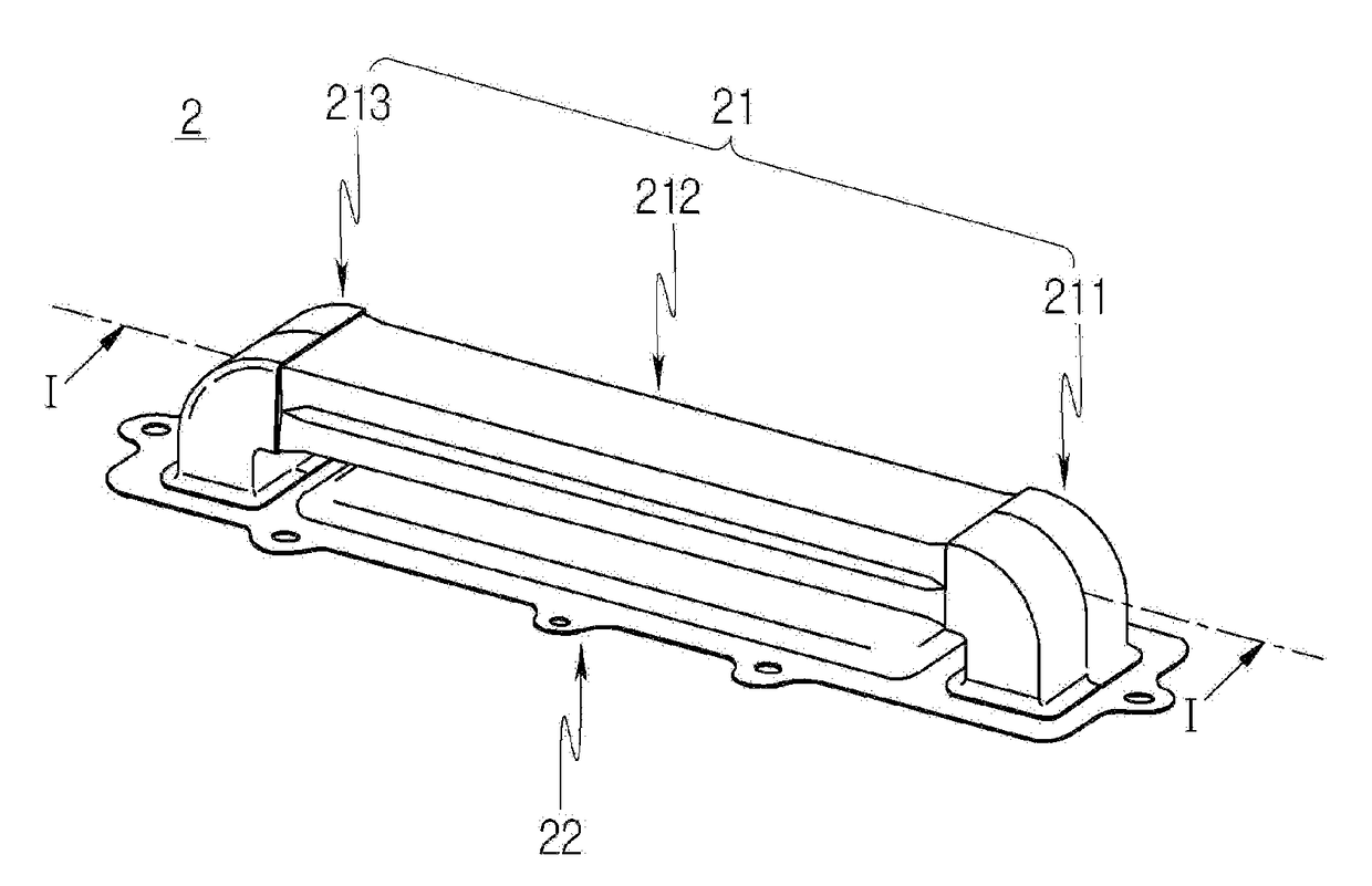
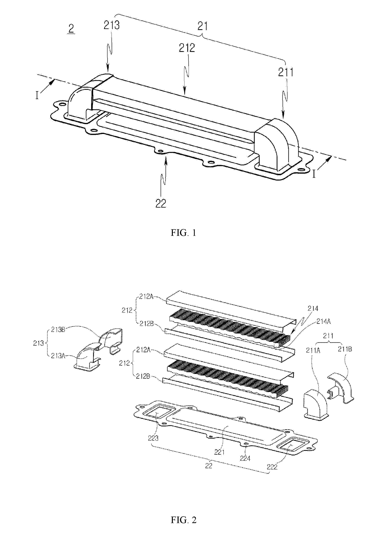
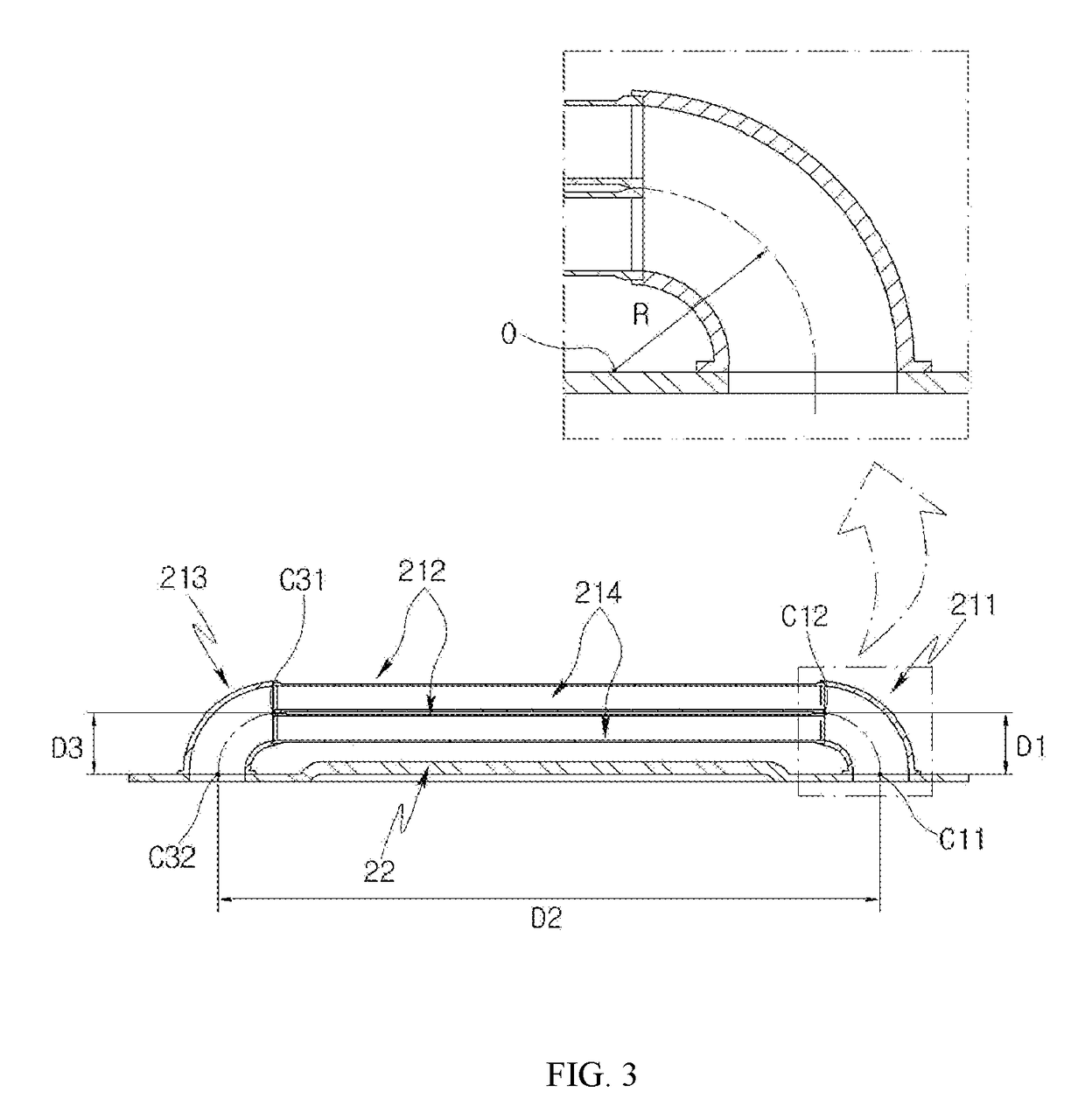
[0042]FIG. 1 is a perspective view illustrating an exhaust gas cooler in accordance with an embodiment of the present invention, FIG. 2 is an exploded perspective view of FIG. 1, FIG. 3 is a sectional view taken along line I-I of FIG. 1, and FIG. 4 is a sectional view showing an exhaust cooler of FIG. 1 mounted to an engine.

[0043]Referring to FIGS. 1 to 4, the exhaust gas cooler 2 in accordance with the embodiment of the present invention may include a heat exchange pipe 21, which is received in cooling water of the engine 1, and through which exhaust gas of the engine 1 passes to exchange heat with the cooling water, and a plate 22 which is provided to mount the heat exchange pipe 21 to the engine 1.

[0044]The heat exchange pipe 21 may include a first pipe unit 211 which communicates with an exhaust gas inlet hole 121, a third pipe uni...


PUM


Abstract

Disclosed herein is an exhaust gas cooler. The exhaust gas cooler may include a heat exchange pipe received in cooling water of an engine, and through which exhaust gas of the engine passes to exchange heat with the cooling water, and a plate configured to mount the heat exchange pipe to the engine. The heat exchange pipe may include a first pipe unit communicating with an inlet hole for exhaust gas and changing a flow direction of exhaust gas drawn from the inlet hole, a second pipe unit communicating with the first pipe unit, and a third pipe unit communicating with an exhaust gas return hole and the second pipe and changing a flow direction of exhaust gas to guide the exhaust gas to the return hole. A heat dissipation fin may be provided in an internal passage of the second pipe unit.

Description

TECHNICAL FIELD[0001]Exemplary embodiments of the present invention relates to an exhaust gas cooler, and more particularly, to an exhaust gas cooler which is mounted to an engine, in which some exhaust gas recirculates into a combustion chamber, so as to cool recirculation exhaust gas of the engine.BACKGROUND ART[0002]Generally, exhaust gas of vehicles contains a large amount of harmful substances such as carbon monoxides, nitrogen oxides, and hydrocarbon Particularly, the production rate of harmful substances such as nitrogen oxides increase as the temperature of an engine is increased.[0003]Nowadays, exhaust gas regulations in each country are being reinforced. To meet such reinforced exhaust gas regulations of each country, an exhaust gas recirculation (EGR) apparatus is provided in a vehicle as a means for reducing harmful substances such as nitrogen oxides contained in exhaust gas.[0004]The EGR apparatus supplies some exhaust gas of the vehicle along with mixing air into a com...

Claims


Application Information

Patent Timeline
Patent Type & Authority Applications(United States)
IPC IPC(8): F02M26/32
CPCF02M26/32F28D7/1661F28D2021/0026F28F9/013F28D7/08F28D7/1684F28D9/0031F28D21/0003F28D2021/008F28F1/04F28F9/002F28F9/02F28F9/0234F28F2009/0285F28F2280/06
Inventor JEONG, SUN ANCHUN, TAE SOO
Owner HANON SYST
Why Eureka
Try Eureka