Efficient industrial waste gas treatment method

An industrial waste gas, high-efficiency technology, applied in gas treatment, separation methods, chemical instruments and methods, etc., can solve the problems of different lamp working efficiency, temperature difference working efficiency, unfavorable emissions, etc., to achieve uniform work and cooling, Good cooling effect and smooth circulation

Pending Publication Date: 2021-07-02
龚才荣
View PDF0 Cites 1 Cited by
  • Summary
  • Abstract
  • Description
  • Claims
  • Application Information

AI Technical Summary

Problems solved by technology

[0003] 1. When the ultraviolet lamp is irradiated, it will generate heat. Generally, it is necessary to install a cooling device outside it, but the structure installed on the periphery of the lamp will affect its working efficiency, resulting in the insufficient ultraviolet light generated. In addition, the installation position of the lamp tube and the air intake setting are fixed, which will lead to the difference in the working efficiency of the internal lamp tube in the square shell because the air intake is in the middle, so the use of heat dissipation will also cause problems. The difference, which in turn leads to deviations in the service life of each lamp tube, and the temperature difference will also lead to a large difference in work efficiency, resulting in the treatment of exhaust gas not reaching the standard treatment rate, which is not conducive to subsequent emissions;
[0004] 2. It is not very efficient to use ultraviolet radiation alone when treating waste gas, so the existing shells are designed to contain TiO 2 The medium is used as a catalyst, and its sol is dispersed on the metal mesh. In order to make the catalytic efficiency high, it is not installed on the inner wall of the shell but in the middle, so that when the exhaust gas is introduced, the wind resistance is particularly special due to its mesh-like structural design. Large, which leads to a great drop in work efficiency, which is not conducive to use in large factories or factories with large exhaust gas output

Method used


Image

  • Efficient industrial waste gas treatment method
  • Efficient industrial waste gas treatment method
  • Efficient industrial waste gas treatment method

Examples


Embodiment Construction

[0029] The following will clearly and completely describe the technical solutions in the embodiments of the present invention with reference to the accompanying drawings in the embodiments of the present invention. Obviously, the described embodiments are only some, not all, embodiments of the present invention. Based on the embodiments of the present invention, all other embodiments obtained by persons of ordinary skill in the art without making creative efforts belong to the protection scope of the present invention.

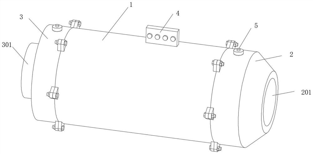
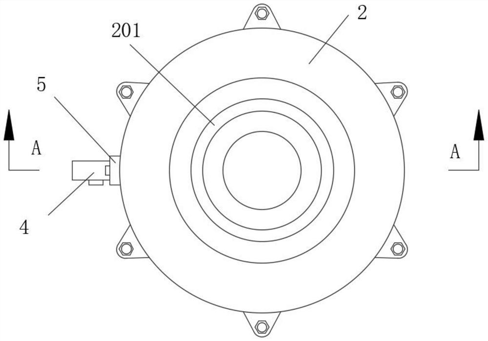
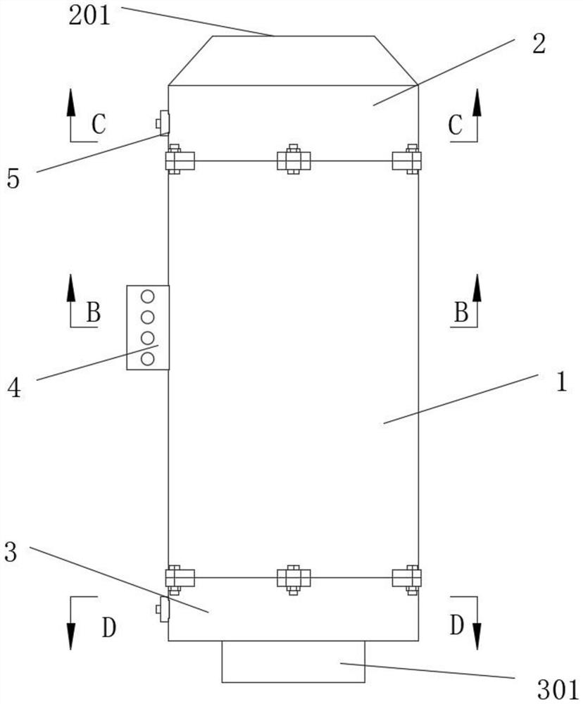
[0030] see Figure 1-9 , a photo-oxygen purifier for industrial waste gas treatment, comprising a housing 1, an air intake head 2 is fixedly installed on one side of the housing 1, an air inlet 201 is opened in the middle of the outer end surface of the air intake head 2, and an air inlet 201 is opened on the other side of the housing 1 An air outlet head 3 is fixedly installed on one side, an air outlet 301 is opened in the middle of the outer end surface of ...


PUM


Abstract

The invention relates to the technical field of environmental protection, and discloses an efficient industrial waste gas treatment method.The efficient industrial waste gas treatment method comprises a shell, a gas inlet head is fixedly installed on one side of the shell, a gas outlet head is fixedly installed on the other side of the shell, the inner wall of the shell is movably sleeved with a first titanium cylinder, and a third titanium cylinder is fixedly installed in the middle of the shell; a second titanium cylinder is movably installed in the position, between the first titanium cylinder and the third titanium cylinder, in the shell, and lamp tubes are annularly, evenly and movably installed in the positions, between the adjacent titanium cylinders, in the shell. The shell is designed to be cylindrical, and the cylindrical titanium cylinders and lamp tubes are arranged in the shell uniformly in a movable manner, a metal net containing TiO2 sol is replaced by the metal cylinders, a net-shaped structure is not adopted, and the titanium cylinders in the shell are designed into structures with different lengths, so that the cooling effect on the lamp tubes is improved, the wind resistance of gas circulation is reduced, and the purification efficiency is improved.

Description

technical field [0001] The invention relates to the technical field of environmental protection, in particular to an efficient industrial waste gas treatment method. Background technique [0002] Industrial waste gas is a major source of pollution today. In order to protect the environment and sustainable development, the treatment of waste gas is extremely critical. For dusty gases, filtration or wet methods can be used to remove them, but for some odorous gases, photo-oxygen purifiers are required. The principle of treatment is to use ultraviolet light to irradiate the gas. On the one hand, the molecular chains in the gas will have a cracking effect, causing them to degrade and turn into compounds. On the other hand, the oxygen molecules in the air will generate free oxygen (active oxygen), and then Combined with oxygen molecules to generate ozone to purify, this kind of purifier is widely used, cost-effective and adaptable, but there are still certain problems in practice...

Claims


Application Information

Patent Timeline
Patent Type & Authority Applications(China)
IPC IPC(8): B01D53/00B01D53/88
CPCB01D53/007B01D53/885B01D2255/20707B01D2255/802B01D2258/02B01D2259/804
Inventor 不公告发明人
Owner 龚才荣
Why Eureka
Try Eureka