Optical user interface system for automotive modules

a technology of user interface and automotive modules, applied in the field of optical user interfaces for, can solve the problems of accumulating debris, significant increasing the probability of static discharge into the electronic circuit to which the switch is connected, and inherently difficult to locate and activate the switch

Inactive Publication Date: 2010-10-19
GENTEX CORP
View PDF25 Cites 97 Cited by
  • Summary
  • Abstract
  • Description
  • Claims
  • Application Information

AI Technical Summary

Benefits of technology

[0006]The present invention overcomes these problems by enabling an operator to control an electronic device, such as a lamp, audio system, mirror, camera, or other electronic device providing for user input, by placing a hand in the vicinity of the device or device input. The invention further provides for the utilization of existing structures, such as a rearview assembly in a vehicle, for the location of the user interface system, minimizing or eliminating the need to provide new surface area for the user interface portion of the system. The present invention still further provides for design flexibility, enabling the implementation of complex and sophisticated input devices without the need for complicated mechanical interfaces. The present invention is particularly well suited for use in a rearview assembly in a vehicle.

Problems solved by technology

This may be difficult at best during nighttime conditions or when the buttons are not easily seen by the operator.
Thus, switches for illuminators are inherently difficult to locate and activate.
Another problem associated with manual switches is the significant increased probability of static discharge into the electronic circuit to which the switch is connected.
Another problem with switches requiring manual contact is that they accumulate debris and can transmit germs from one operator to another.
The accumulated debris may also come between the electrical contacts and thus affect the reliability of the switch.
Switches that require mechanical movement and contact, which include electromechanical switches, membrane switches, etc., are prone to wear and are often the most unreliable portion of an electronic system.
Also, many switch types do not function very well in a high moisture environment or in the presence of frost, as would occur in many vehicles.
An additional problem with such switches is that most of the switch types are costly to make and difficult and costly to assemble into conventional circuit assemblies compared to the cost of incorporating other standard electronic components.
Further, manual switches require an ordinate focus / concentration, distracting operators from safely executing their primary task.
Locating manual switches in vehicles to control vehicle electronic devices or accessories can also be problematic for a number of reasons.
Button space in or near the electronic devices can be limited.
Switch backlights to assist the occupants in locating the manual switches are often necessary, but can be distracting to vehicle occupants and the driver.
More complex vehicle electronic systems, such as telematics systems, often require sophisticated input means such as, for example, pointing devices, which can be difficult to implement in a mechanical or manual switch.

Method used


Image

  • Optical user interface system for automotive modules
  • Optical user interface system for automotive modules
  • Optical user interface system for automotive modules

Examples


Embodiment Construction

[0031]Reference will now be made, in detail, to the preferred embodiments of the invention, examples of which are illustrated in the accompanying drawings. Whenever possible, the same reference numerals will be used throughout the drawings to refer to the same or like parts.

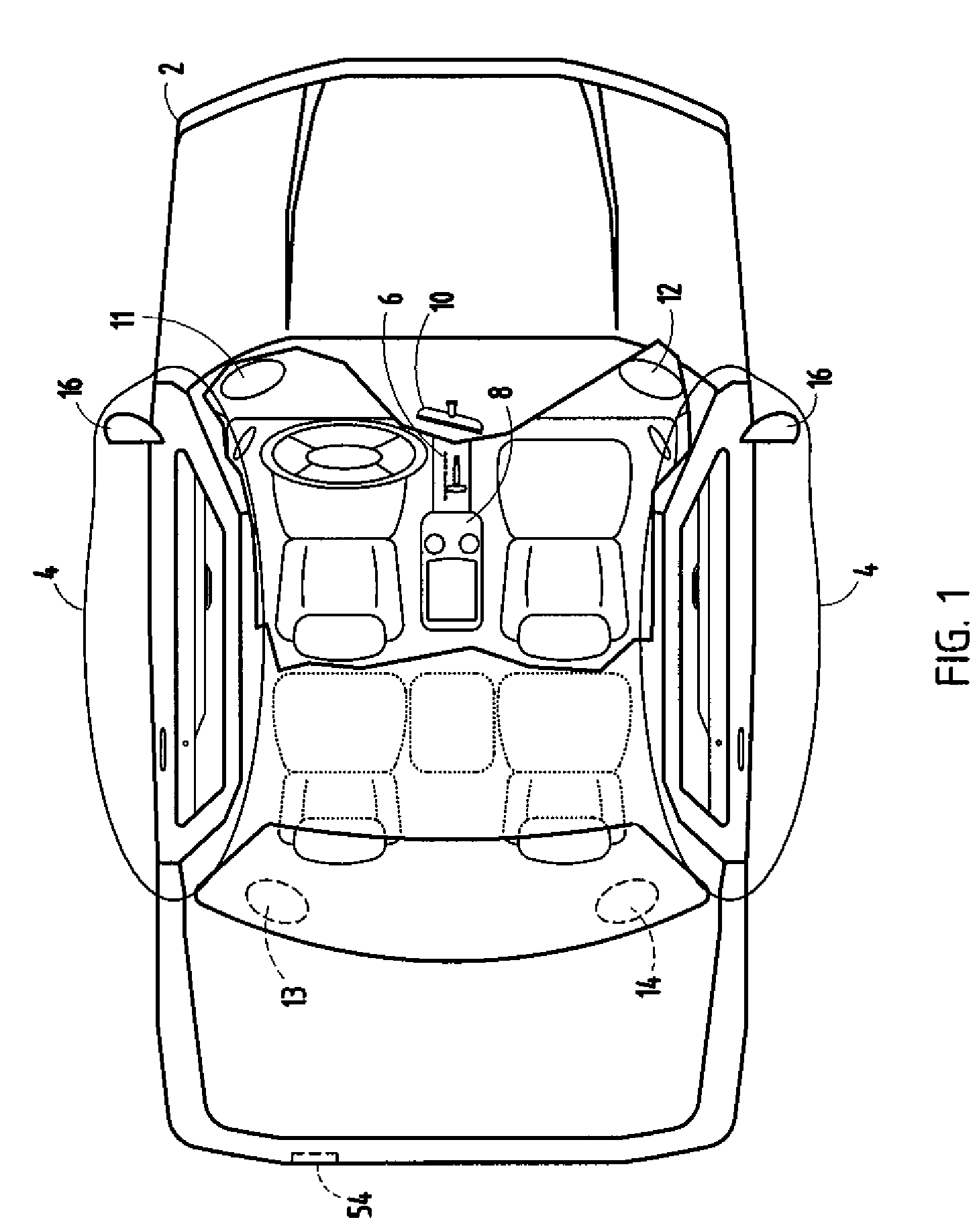
[0032]The present invention and its various aspects are generally described as being implemented in a vehicle. FIG. 1 provides a general illustration of a vehicle 2, incorporating various embodiments of the present invention. As shown, vehicle 2 includes vehicle doors 4 for ingress and egress into the vehicle. Each of vehicle doors 4 includes an external rearview mirror 16 for providing a view to the rear of the vehicle. Vehicle 2 also includes transmission control 6 for allowing a driver of the vehicle to control the transmission of the vehicle 2. As shown, vehicle 2 also includes floor console 8, which provides multiple areas for retaining cups in an upright position, and also includes armrest areas for the dri...


PUM


Abstract

A rearview assembly for a vehicle including a mounting structure for mounting to a vehicle, a rearward viewing device, and housing with a position sensor, is provided. The position sensor includes first and second radiation emitters, a radiation reception element, and sensor processing circuitry coupled to one of the position sensors and the radiation reception element. The position sensor determines the position of an object in the vicinity of the rearward viewing device.

Description

BACKGROUND OF THE INVENTION[0001]The present invention generally relates to optical user interfaces for controlling electronic devices, and more particularly to optical user interfaces for controlling electronic devices coupled to an automobile.[0002]Preexisting electronics devices and accessories, specifically those located in a vehicle, typically utilize manual switches that require manual contact for the electronic device or accessory to be controlled. The requirement for manual contact presents several drawbacks. First, manual contact requires that an operator know and / or see the switch location precisely. This may be difficult at best during nighttime conditions or when the buttons are not easily seen by the operator. This can frequently happen in an automobile, where switches may be relatively small to accommodate multiple functions, and where the switch location is such that the driver must divert his or her eyes from the road ahead. When the device or accessory to be activat...

Claims


Application Information

Patent Timeline
Patent Type & Authority Patents(United States)
IPC IPC(8): B60Q1/00
CPCB60Q3/023B60Q3/0233B60Q3/024B60Q3/0243B60Q3/0293B60R1/12G09G3/14B60R2001/1215B60R2001/1223B60Q3/258B60Q3/267B60Q3/283B60Q3/80B60Q3/229B60Q3/20
Inventor TURNBULL, ROBERT R.BLAKER, DAVID A.BRYSON, MICHAEL A.PLANGGER, DAVID L.POE, G. BRUCEWATSON, ALAN R.
Owner GENTEX CORP
Why Eureka
Try Eureka