Zoom lens and image capture apparatus
a technology of zoom lens and image capture device, which is applied in the direction of mountings, optics, instruments, etc., can solve the problems of complicated construction of zoom barrel, and achieve the effect of high performance and compactness, and sufficient back focus
- Summary
- Abstract
- Description
- Claims
- Application Information
AI Technical Summary
Benefits of technology
Problems solved by technology
Method used
Image
Examples
first embodiment
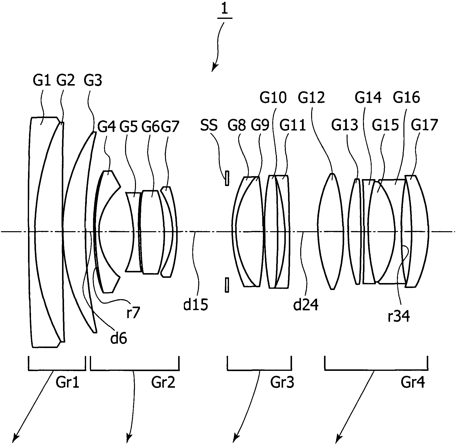
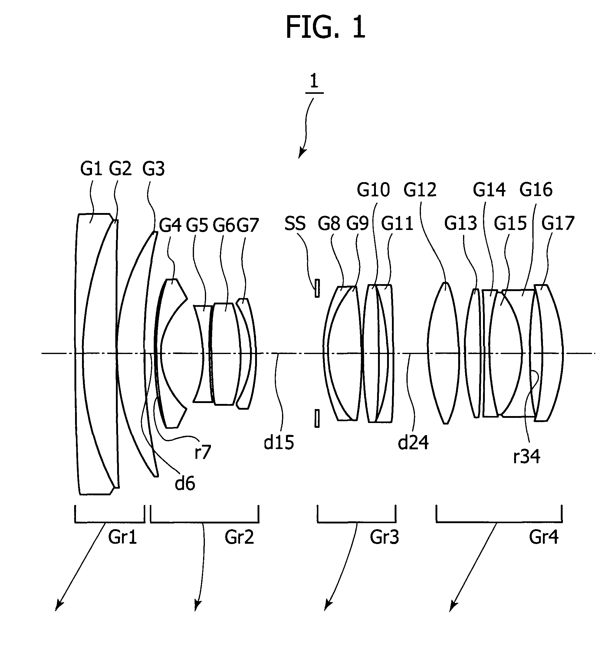
[0045]FIG. 1 shows the lens construction at the wide-angle end of a zoom lens 1 indicating, with arrows, motion loci of its constituent lens groups along the optical axis toward the telephoto end, respectively.
[0046]The zoom lens 1 includes, in the following order from the object side, a first lens group Gr1 having positive refractive power, a second lens group Gr2 having negative refractive power, a third lens group Gr3 having positive refractive power, and a fourth lens group Gr4 having positive refractive power. During zooming from the wide-angle end to the telephoto end, the first to fourth lens groups move toward the object side as indicated by the arrows, respectively, in FIG. 1 such that the distance between the first lens group Gr1 and the second lens group Gr2 increases, the distance between the second lens group Gr2 and the third lens group Gr3 decreases, and the distance between the third lens group Gr3 and the fourth lens group Gr4 decreases. Further, the second lens gr...
second embodiment
[0056]FIG. 5 shows the lens construction at a wide-angle end of a zoom lens 2 indicating, with arrows, motion loci of its constituent lens groups along the optical axis toward a telephoto end, respectively.
[0057]The zoom lens 2 includes, in the following order from the object side, a first lens group Gr1 having positive refractive power; a second lens group Gr2 having negative refractive power; a third lens group Gr3 having positive refractive power; and a fourth lens group Gr4 having positive refractive power. During zooming from the wide-angle end to the telephoto end, the first to fourth lens groups move toward the object side as indicated by the arrows, respectively, in FIG. 5 such that a distance between the first lens group Gr1 and the second lens group Gr2 increases, a distance between the second lens group Gr2 and the third lens group Gr3 decreases, and a distance between the third lens group Gr3 and the fourth lens group Gr4 decreases. Further, the second lens group Gr2 mo...
third embodiment
[0067]FIG. 9 shows the lens construction at a wide-angle end of a zoom lens 3 indicating, with arrows, motion loci of its constituent lens groups along the optical axis toward a telephoto end, respectively.
[0068]The zoom lens 3 includes, in the following order from the object side, a first lens group Gr1 having positive refractive power; a second lens group Gr2 having negative refractive power; a third lens group Gr3 having positive refractive power; and a fourth lens group Gr4 having positive refractive power. During zooming from the wide-angle end to the telephoto end, the first to fourth lens groups move toward the object side as indicated by the arrows, respectively, in FIG. 9 such that a distance between the first lens group Gr1 and the second lens group Gr2 increases, a distance between the second lens group Gr2 and the third lens group Gr3 decreases, and a distance between the third lens group Gr3 and the fourth lens group Gr4 decreases. Further, the second lens group Gr2 mo...
PUM
 Abstract
Description
Claims
Application Information
 - R&D
- Intellectual Property
- Life Sciences
- Materials
- Tech Scout
- Unparalleled Data Quality
- Higher Quality Content
- 60% Fewer Hallucinations
Browse by: Latest US Patents, China's latest patents, Technical Efficacy Thesaurus, Application Domain, Technology Topic, Popular Technical Reports.
© 2025 PatSnap. All rights reserved.Legal|Privacy policy|Modern Slavery Act Transparency Statement|Sitemap|About US| Contact US: help@patsnap.com


