External high pressure fluid reservoir for riser tensioner cylinder assembly

a technology of fluid reservoir and riser, which is applied in the direction of sealing/packing, mechanical equipment, and well accessories, etc., can solve the problem of reducing the volume of gas that can be filled, and achieve the effect of reducing or eliminating

Active Publication Date: 2010-10-26
VETCO GRAY LLC
View PDF35 Cites 20 Cited by
  • Summary
  • Abstract
  • Description
  • Claims
  • Application Information

AI Technical Summary

Benefits of technology

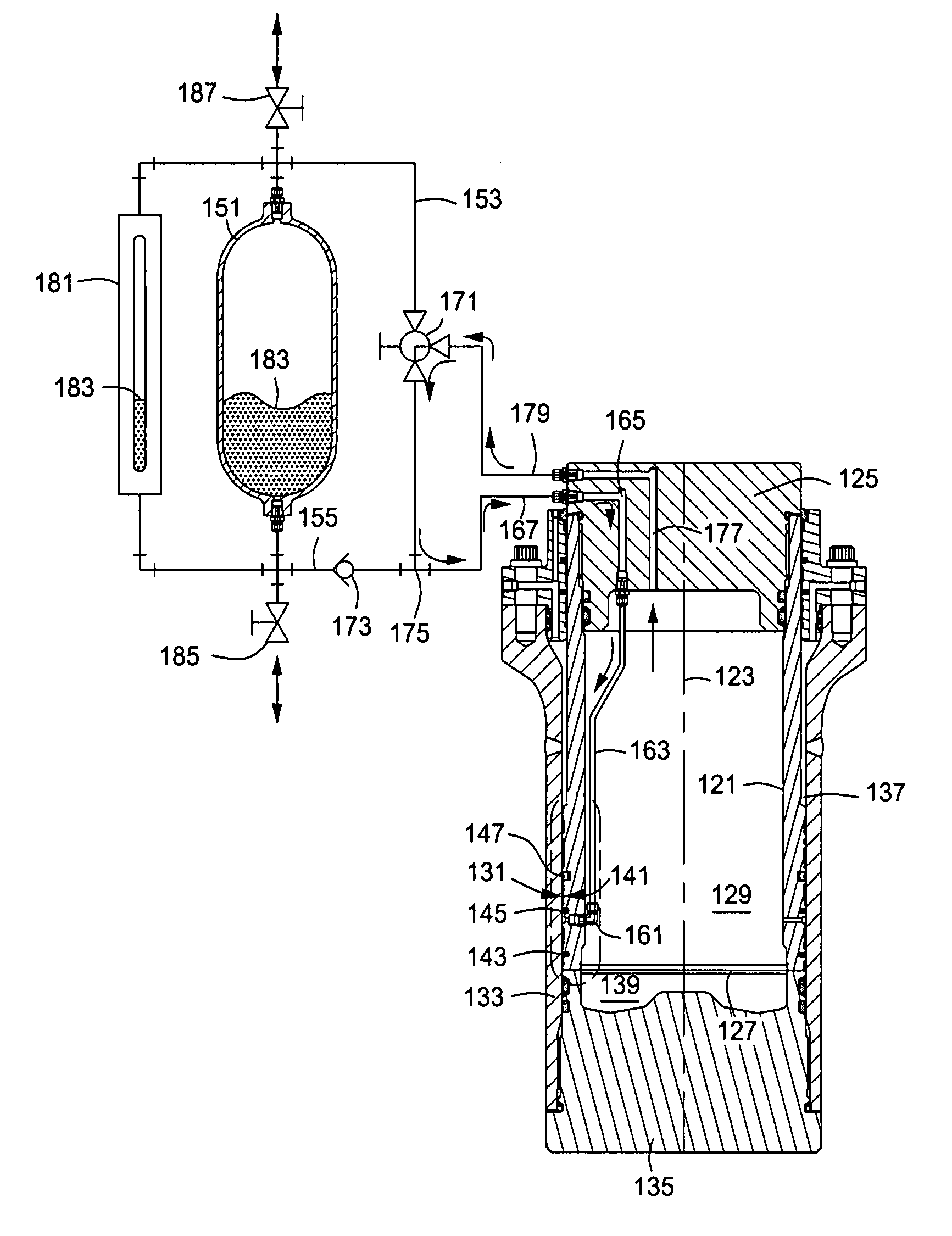
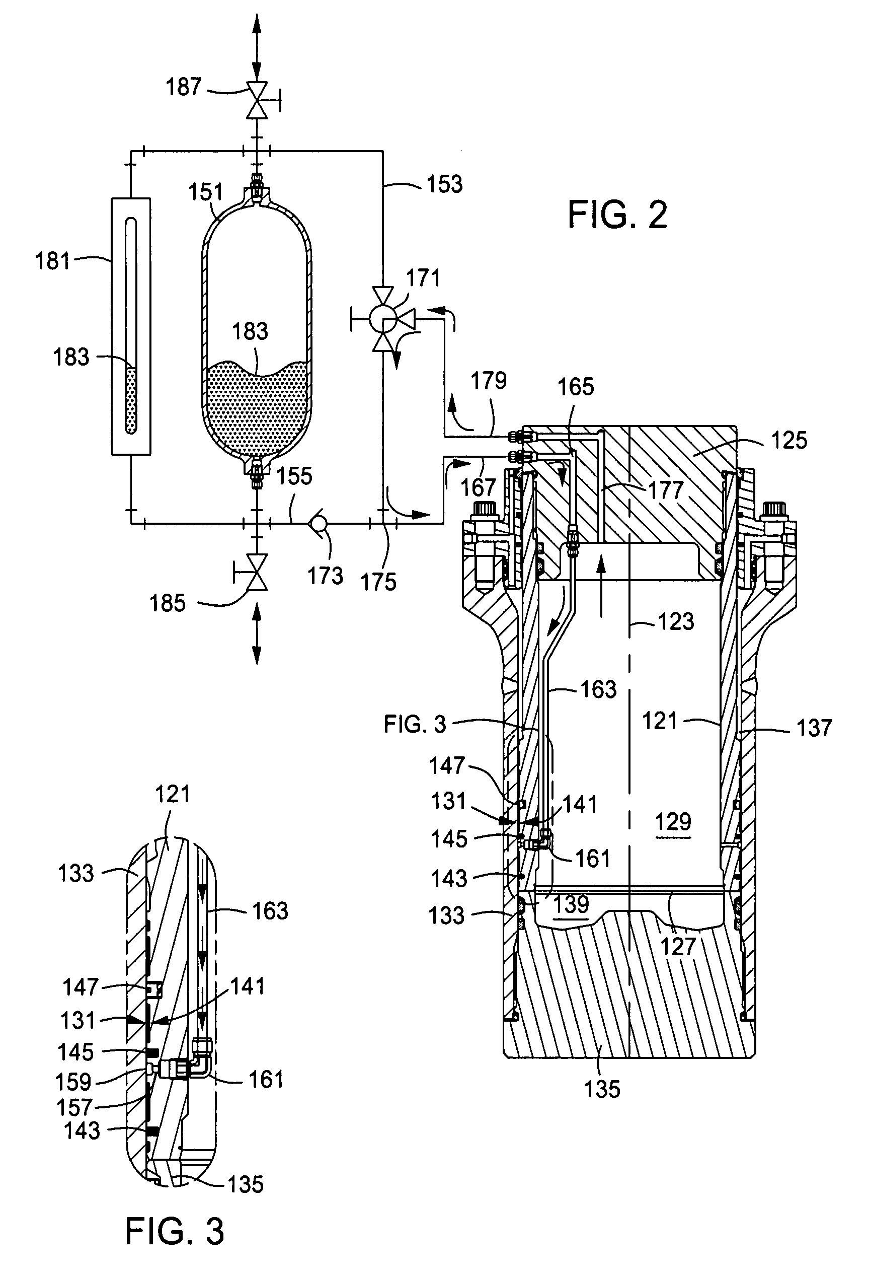
[0007]One embodiment of a system, method, and apparatus for a riser tensioner has inner and outer cylindrical barrels that telescopingly engage each other. An external fluid reservoir or tank is mounted outside of the barrels for communicating a small quantity of hydraulic fluid or other media to the working or dynamic seals between the inner and outer cylinder barrels. By using a small external reservoir, the internal volume of the cylinder rod assembly is made available for storage of nitrogen gas or compressed air. By increasing the internal gas volume of the cylinder rod, a “softer” cylinder is employed which has the positive effect of reducing or eliminating the need for external storage tanks or accumulator-type devices.
[0008]The external reservoir also offers a service improvement in that the cylinder fluid level is easily checked by using a sight glass or calibrated liquid level gage. Another improvement of the invention is that the reservoir is readily isolated from the cylinder assembly by a combination of check and three-way valves. This improvement allows easier access to the working fluid and allows the addition or removal of high pressure fluid to the system without the requirement of a high pressure fluid cart.
[0010]The small external reservoir is connected to the ports leading from the three-way isolation valve and check valve. One of the valves allows high pressure gas bleed off from the external reservoir. Fill and drain valves allow the addition or removal of fluid from the tank. Filling or draining the tank is accomplished without a high pressure fluid cart by simply positioning the three-way isolation valve such that the pressure is routed back to the cylinder, which will allow the external reservoir to be bled down and vented to atmosphere. The annular groove in the cylinder rod communicates with a radial hole or port and allows the high pressure fluid to access the primary and secondary seals. A zero differential pressure seal below the annular groove prevents fluid leakage due to the effect of gravity.

Problems solved by technology

However, provisions must be made for lubrication of the primary seals, and the hydraulic fluid reduces the amount of volume that can be filled with gas.

Method used


Image

  • External high pressure fluid reservoir for riser tensioner cylinder assembly
  • External high pressure fluid reservoir for riser tensioner cylinder assembly
  • External high pressure fluid reservoir for riser tensioner cylinder assembly

Examples


Embodiment Construction

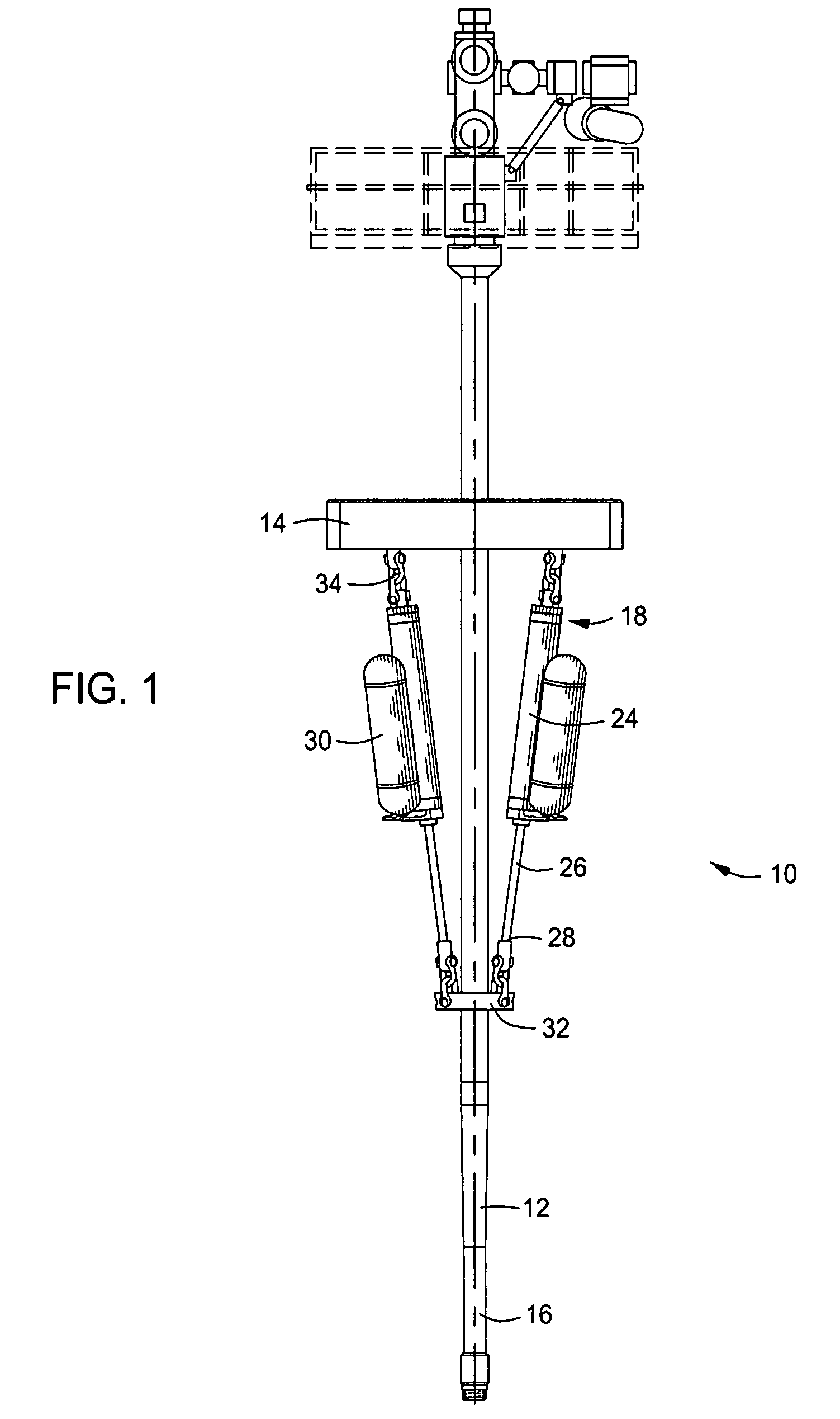
[0018]Referring to FIG. 1, one type of riser tensioning mechanism 10 is depicted. Although mechanism 10 is depicted as a “pull-up” type, one skilled in the art will recognize that the present invention is equally suitable for “push-up” type and other types of tensioning mechanisms.

[0019]A riser 12 extends downwardly from a platform 14 to a subsea wellhead (not shown). Riser 12 has a longitudinal axis 16 and is surrounded by a plurality of hydraulic cylinders 18. Each hydraulic cylinder 18 has a cylinder housing 24 having a chamber (not shown). A piston rod 26 has a rod end 28 that extends downward from each cylinder housing 24 and hydraulic cylinder 18. The piston ends of rods 26 opposite rod ends 28 are disposed within the respective chambers (not shown) of cylinder housings 24. Hydraulic fluid (not shown) is contained within the housing 24 for pulling piston rods 26 upward. Each hydraulic cylinder 18 also may comprise an accumulator 30 for accumulating hydraulic fluid from hydraul...


PUM


Abstract

A riser tensioner has inner and outer cylindrical barrels that telescopingly engage each other. A small external tank is mounted outside of the barrels for communicating a small quantity of hydraulic fluid the seals between the inner and outer barrels. The external tank allows the internal volume of the cylinder rod assembly to be used for gas storage and reduces the need for accumulators. The fluid level in the external tank is checked via a sight glass, and the tank is isolated from the cylinder assembly by a combination of check and three-way valves, which allows easier access to the working fluid, and allows the addition or removal of high pressure fluid to the system without a high pressure fluid cart.

Description

[0001]This application is a continuation-in-part of U.S. patent application Ser. No. 11 / 280,118, filed Nov. 16, 2005, and is incorporated herein by reference.BACKGROUND OF THE INVENTION[0002]1. Technical Field[0003]The present invention relates in general to riser tensioners for offshore platform drilling and production floating platforms and, in particular, to tensioner cylinder assemblies having a high pressure external fluid reservoir for lubricating seals between the cylinders.[0004]2. Description of the Related Art[0005]Risers are used in offshore oil and gas well production for conveying well fluids from a subsea wellhead to a floating production platform. Tensioners are employed at the platform to apply tension to the risers. A typical tensioner comprises a telescoping piston and cylinder arrangement supplied with gas pressure from accumulators. Waves and currents cause the piston and cylinder to extend and retract. Hydraulic fluid within the chamber provides lubrication.[000...

Claims


Application Information

Patent Timeline
Patent Type & Authority Patents(United States)
IPC IPC(8): E21B17/07
CPCE21B19/002E21B19/006F16L1/23
Inventor ELLIS, FIFE B.
Owner VETCO GRAY LLC
Why Eureka
Try Eureka