Deflecting device for an offset frontal collision for motor vehicles

a technology for frontal collisions and deflectors, which is applied in vehicle bodies, monocoque constructions, and understructures. it can solve the problems of affecting the safety of passengers, the risk of particular wheels penetrating the passenger compartment, and the presence of hazardous phenomena. it achieves the effect of more impact energy and high collision speed

Inactive Publication Date: 2010-10-26
MAGNA STEYR FAHRZEUGTECHN
View PDF15 Cites 73 Cited by
  • Summary
  • Abstract
  • Description
  • Claims
  • Application Information

AI Technical Summary

Benefits of technology

[0009]According to the invention, this is achieved in that the deflecting device forms a kinematic chain which is situated approximately in a horizontal plane and the coupling link of which is a deflector which, under the action of a frontal impact, pivots rearward positively guided and is displaced toward the outside of the vehicle. The displacement of the deflector to the outside causes it to embrace and grasp the wheel securely from the outside without destroying it at this early stage. This already has a positive effect on the form taken by the damage. At the same time, a positive turning in of the wheel can occur as a positive side effect. If the wheel is destroyed in the further course of the collision, it has already fulfilled its task—that of deflecting the collision counterpart and of preventing intrusions. It is noticeable that this effect reliably occurs without additional measures, merely by means of the collision energy itself.
[0011]In the second embodiment, the kinematic chain is a slider crank mechanism which comprises a swinging arm which is pivotable about bearings connected to the longitudinal member, a further bearing, a sliding guide and the coupling link which is connected to the outer end of the swinging arm at a pivot point and is guided in the further bearing and reaches beyond the outer pivot point of the vehicle. Among other things, the sliding guide affords the advantage of being able to be designed with a narrow fit, so that it provides a certain resistance to an initial displacement.
[0017]Finally, in a development of the inventive concept, the further bearing is fitted on the longitudinal member behind a crashbox (24) forming the front end thereof (claim 11). It is therefore ensured, in the event of a collision with a greater degree of offset and higher collision speed, that the deflector cannot be pivoted. In this case, the wheel concerned cannot pivot inward and the impact path via the wheel to the sill is not interrupted. As a result, in the event of severe collisions, more impact energy can be absorbed.

Problems solved by technology

In vehicles, this lateral part of the front end of the vehicle in front of the passenger compartment is usually less rigid than the central part in front of the passenger compartment and also absorbs less collision energy, resulting in considerable deformations of the passenger compartment.
In particular, there is the risk of the particular wheel penetrating the passenger compartment.
Furthermore, in the case of collisions of this type, a particularly hazardous phenomenon also occurs: even in the event of a relatively small offset, the collision-side front wheels of the two vehicles become interlocked; one wheel at least of the one vehicle collides with the wheel suspension of the other, and vice versa.
In addition, the two interlocked vehicles are jointly also caused to twist about the vertical axis.
It is conceivable that the bumper may never be strong enough for this purpose at the collision speeds customary nowadays.
However, these deflecting plates are also constructed in a very heavy manner if they are actually to have this effect, and they likewise require a particularly heavy bumper involving the abovementioned disadvantages.
However, above all, the effect of the front deflecting plate is inadequate for kinematic reasons: if it is arranged at a sufficient distance in front of the wheel and does not extend over the outer vertical boundary surface of the wheel, its outer end pivots inward on a circular arc.

Method used


Image

  • Deflecting device for an offset frontal collision for motor vehicles
  • Deflecting device for an offset frontal collision for motor vehicles
  • Deflecting device for an offset frontal collision for motor vehicles

Examples


Embodiment Construction

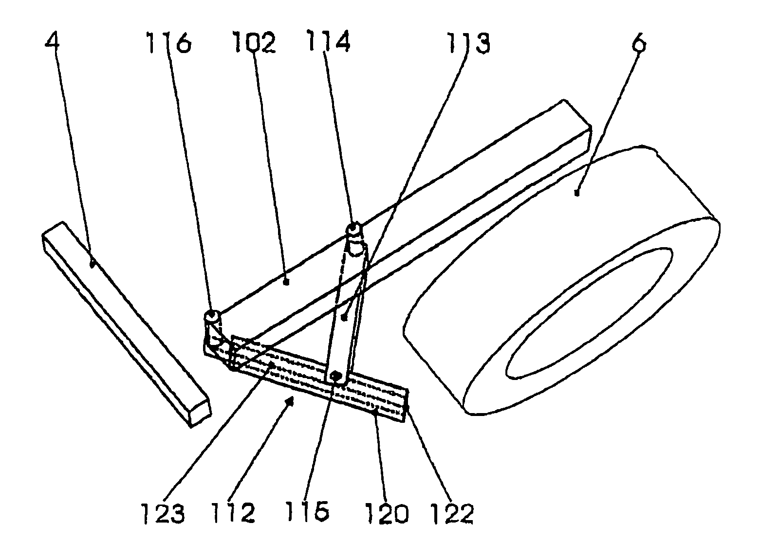
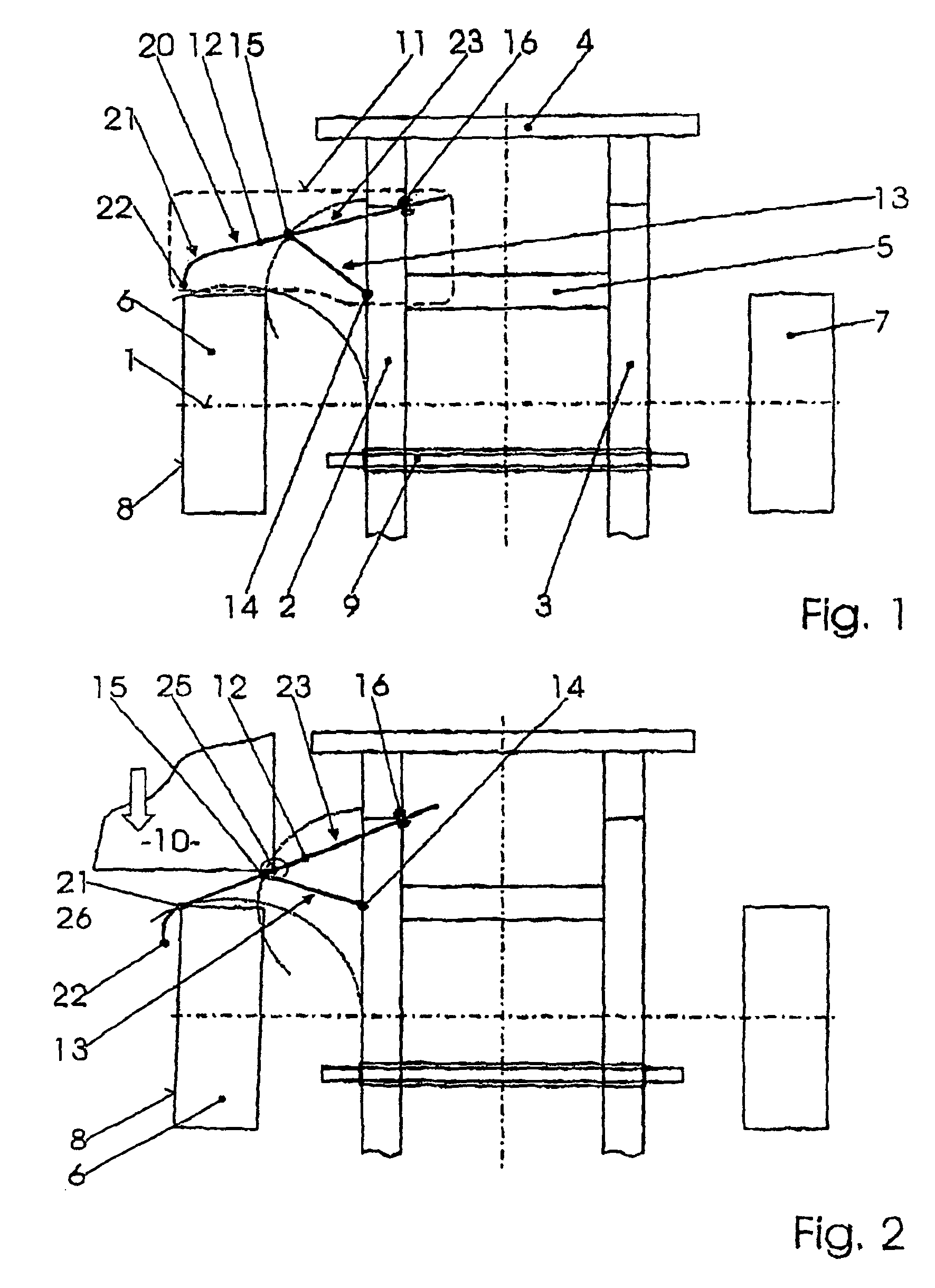
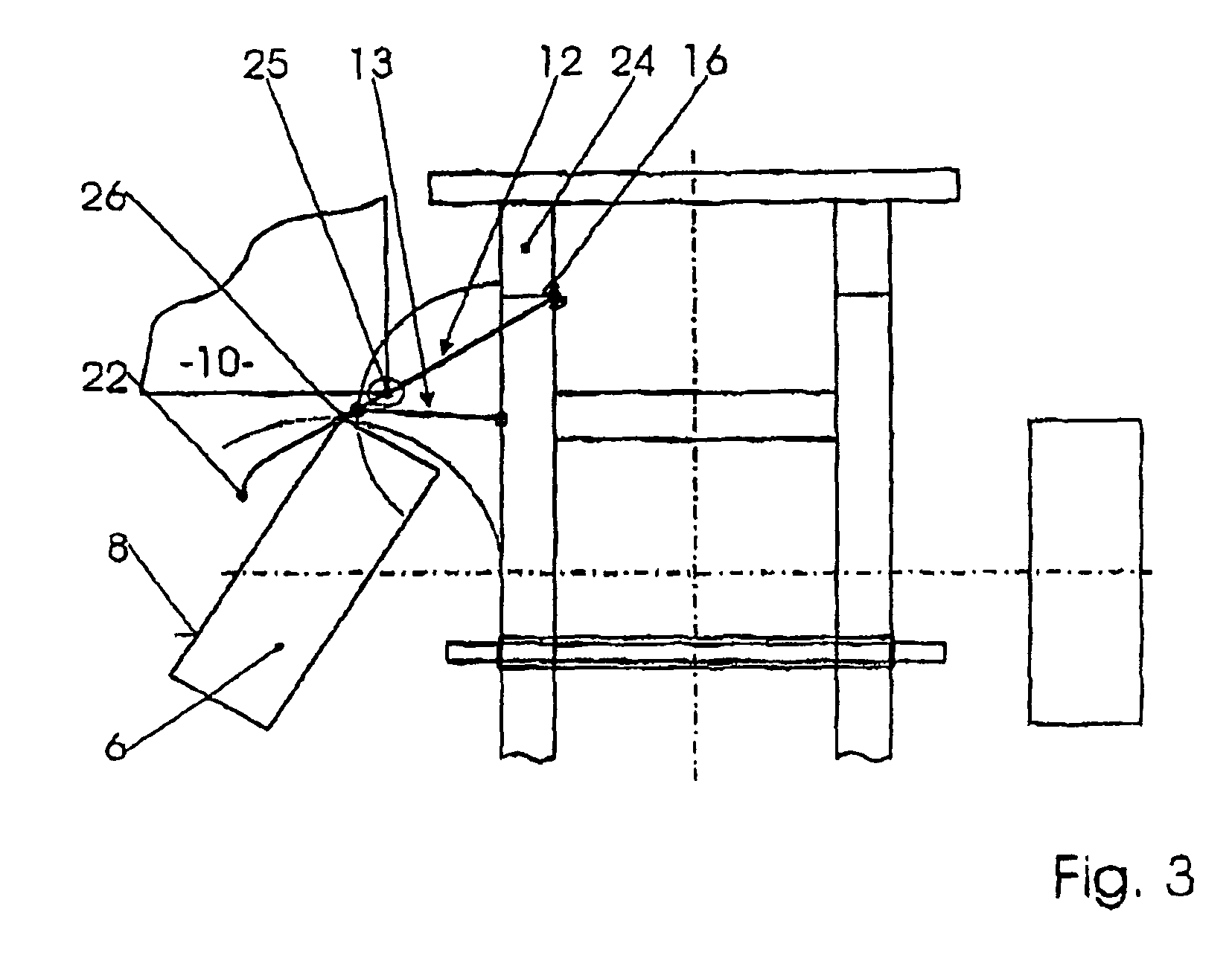
[0029]In FIG. 1, the front end of a motor vehicle is indicated only by means of its two longitudinal members 2, 3, a bumper support 4, a crossmember 5 and the centerline 1 of the front axle. In the following text, only the left side with the left front wheel 6 and the left longitudinal member 2 is described; however, the same also applies to the right side of the vehicle with the right front wheel 7 and the right longitudinal member 3. Furthermore, the steering mechanism 9 of a rack and pinion steering system, which steering mechanism is arranged behind the front axle, is also indicated.

[0030]A deflecting device 11 according to the invention which is surrounded as a whole by a dashed line is situated in front of the left front wheel 6, the outer vertical boundary surface of which is denoted by 8. The deflecting device 11 comprises a deflector 12 and a swinging arm 13 which form a kinematic chain, here a slider crank mechanism. The swinging arm 13 is pivotable in a bearing 14 connect...


PUM


Abstract

In a motor vehicle, a deflecting device (11) for an offset frontal collision for the motor vehicle is arranged in front of a front wheel (6). In order, in the event of a collision, to safely pivot the front wheel inward, the deflecting device (11) forms a kinematic chain, the coupling link of which is a deflector (12) which, under the action of a frontal impact, is pivoted to the rear and is displaced toward the outside of the vehicle. The kinematic chain is a slider crank mechanism comprising a swinging arm (13) which is pivotable about a bearing (14), a further bearing (16), a sliding guide (16) and the coupling link (12) which is connected to the outer end of the swinging arm at a pivot point (15) and is guided in the further bearing (16).

Description

CROSS REFERENCE TO RELATED APPLICATIONS[0001]This case is the U.S. national phase of International Application No. PCT / AT2005 / 000166 filed May 17, 2005 which claims priority of Austrian Application No. GM 361 / 2004 filed May 17, 2004.BACKGROUND OF THE INVENTION[0002]The invention relates to a deflecting device for an offset frontal collision for motor vehicles, the front end of which vehicles has a left and a right longitudinal member, the deflecting device being arranged in front of a front wheel and protecting the front wheel in the event of a collision. An offset frontal collision is to be understood as meaning a frontal collision in which the colliding vehicles move toward each other with directional vectors which are substantially parallel but are offset laterally in relation to one another. The collision zone is therefore only a lateral part of the front end of the vehicle.[0003]In vehicles, this lateral part of the front end of the vehicle in front of the passenger compartment...

Claims


Application Information

Patent Timeline
Patent Type & Authority Patents(United States)
IPC IPC(8): B60R19/00B60R19/16B60R19/26B60R19/38B60R21/00B62D21/15
CPCB60R19/00B60R19/16B62D21/152B60R19/26B60R2019/007B60R2021/0023
Inventor EICHBERGER, ARNOHUBMANN, FRANZPERNKOPF, FRIEDRICHSCHIMPL, WOLFGANGWINKLER, STEPHAN
Owner MAGNA STEYR FAHRZEUGTECHN
Why Eureka
Try Eureka