Atomizer for dispensing liquids for medical purposes

a technology for atomizers and liquids, applied in the direction of liquid transfer devices, single-unit apparatuses, transportation and packaging, etc., can solve the problems of neither the atomizer, nor the solution, nor the aerosol produced, and achieve the effect of stable storag

Active Publication Date: 2010-10-26
BOEHRINGER INGELHEIM INT GMBH
View PDF26 Cites 61 Cited by
  • Summary
  • Abstract
  • Description
  • Claims
  • Application Information

AI Technical Summary

Benefits of technology

[0019]The object of the present invention is now that of providing an atomizer which also makes it possible to store, mix, and administer formulations, in a flow direction, which can be stably stored only under comparatively different conditions such as for example pH-value, solvent, or additives.
[0033]Preferably the valve body is arranged at the end of the hollow plunger, which is the downstream end in the flow direction. That prevents a back-flow of the formulation or the mixed formulations into the hollow plunger.
[0037]The first sub-object of the invention is attained by a cartridge which has a first and a second cartridge chamber wherein a first liquid is stored in a first cartridge chamber and a second liquid is stored in a second cartridge chamber which is spatially separated from the first cartridge chamber. In this case the two liquids are disposed in one cartridge, whereby manageability when inserting the cartridge is simplified.

Problems solved by technology

In addition, they should not have any constituents that can interact with the atomizer, so that neither the atomizer, nor the solution, nor the aerosol produced, suffer damage.

Method used


Image

  • Atomizer for dispensing liquids for medical purposes
  • Atomizer for dispensing liquids for medical purposes
  • Atomizer for dispensing liquids for medical purposes

Examples


first embodiment

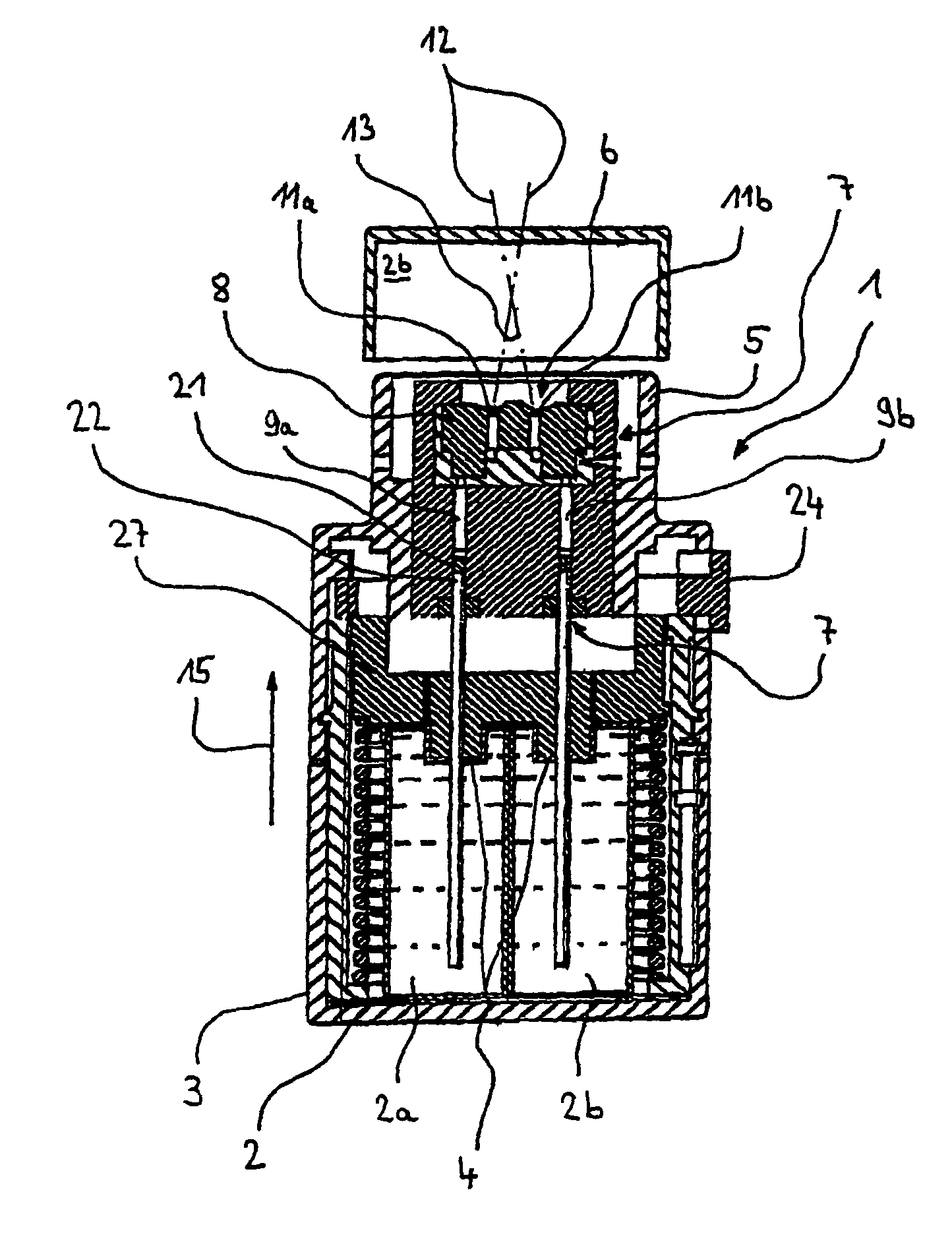
[0048]FIG. 1 shows a view in longitudinal section through the atomizer 1 having a first nozzle body 8a and a second nozzle body 8b and two passages 9a, 9b extending in parallel relationship, with hollow plungers 10a, 10b guided therein, in accordance with a The passages 9a, 9b and the hollow plungers 10a, 10b together form the connecting tube system 7.

[0049]The atomizer includes a housing which is divided into two and which is rotatable relative to each other and by way of which a stressing element 23 can be stressed. Upon actuation of a release button 24 a cup-shaped thrust plate 27 is released and advanced by the spring force of the stressing element 23 in the flow direction 15 (see FIG. 2). In that case the two hollow plungers 10a, 10b which are fixed to the thrust plate 27 and passed therethrough are also advanced, together with the thrust plate 27, and in so doing compress the liquids which were previously sucked into the passages 9a, 9b and which then issue from the first noz...

second embodiment

[0055]FIG. 2 shows the atomizer in which the passages 9a, 9b, in the region of the atomization device 6, extend in a common nozzle body 8 and issue there by way of a separate individual first nozzle outlet 11a and a second individual nozzle outlet 11b.

[0056]As can be seen from FIG. 2 the respective liquids issue at a jet direction 12 and meet in front of the atomizer 1. In that situation the liquids come together at the impingement angle 13. Due to the formulations meeting, particularly fine nebulization and mixing of the formulations is achieved, with an aerosol cloud being produced from the two liquids in this embodiment.

third embodiment

[0057]FIG. 3 shows the invention in which the passage 9 is in the form of a mixing passage 16, that is to say the first passage 9a and the second passage 9b combine in the mixing passage 16. Hollow plungers 10a, 10b are mounted displaceably in respective ones of the passages 9a and 9b.

[0058]In the embodiment of FIG. 3 mixing of the two liquids already takes place in the suction process, that is to say, upon a downward movement of the two hollow plungers 10a, 10b.

[0059]Upon an upward movement of the two hollow plungers 10a, 10b the formulation which has been previously respectively sucked in and which is to be found in the passage 9a, 9b is compressed and expelled in the direction of the nozzle body 8. A nozzle outlet 11a is visible in the view shown in FIG. 3. Mixing of the formulation which is sucked in by way of the hollow plunger 10a from the first cartridge chamber 2a and that which is sucked in by way of the hollow plunger 10b from the second cartridge chamber 2b is therefore...


PUM


Abstract

Atomizers (1) comprising a cartridge holder (4) which is arranged in the housing (3), a mouthpiece (5) which is provided on the housing (3) and in which an atomization device (6) is arranged, and a connecting tube system (7) which connects the atomization device (6) and the cartridge holder (4), wherein the atomization device (6) has at least one nozzle body (8) and the connecting tube system (7) has at least one passage (9) with a hollow plunger (10) mounted displaceably therein, wherein the hollow plunger (10) includes a valve body (21). In accordance with a first embodiment the atomizer (1) has a first hollow plunger (10a) mounted displaceably in a first passage (9a) and a second hollow plunger (10b) mounted displaceably in a second passage (9b), wherein the first hollow plunger (10a) and the second hollow plunger (10b) extend into the cartridge holder (4).

Description

BACKGROUND OF THE INVENTION[0001]1. Field of the Invention[0002]The invention concerns an atomizer for dispensing liquids for medical purposes, for example pharmaceutical active substance formulations, from at least one container for the liquid, which can be fitted into the atomizer (cartridge), as well as a cartridge and a system comprising an atomizer and a cartridge which can be fitted therein.[0003]2. Description of the Prior Art[0004]The known atomizers include as essential units a cartridge holder which is arranged in the housing, a mouthpiece which is provided on the housing and in which an atomization device is arranged, and a connecting tube system which connects the atomization device and the cartridge holder, wherein the atomization device has at least one nozzle body and the connecting tube system has at least one passage with a hollow plunger mounted displaceably therein, wherein the hollow plunger includes a valve body.[0005]The hollow plungers which are inserted in th...

Claims


Application Information

Patent Timeline
Patent Type & Authority Patents(United States)
IPC IPC(8): A62C13/62B05B9/04B05B7/12B05B7/06B67D7/70B67D7/84A61M5/00A61M11/00A61M15/00B05B11/00
CPCA61M15/0065B05B11/3015B05B11/308B05B11/3081B05B11/3084B05B11/3091A61M11/001A61M11/007A61M15/0003A61M15/0036B05B11/1015B05B11/1081B05B11/108B05B11/1084B05B11/1091A61M11/00A61M13/00A61M11/02
Inventor SPALLEK, MICHAELJUNG, ANDREE
Owner BOEHRINGER INGELHEIM INT GMBH
Why Eureka
Try Eureka