Six link independent suspension for a drive axle

a technology of independent suspension and drive axle, which is applied in the direction of resilient suspension, interconnection system, vehicle spring, etc., can solve the problems of many packaging and design constraints of independent suspension system, difficult configuration, and difficult to achieve configuration

Active Publication Date: 2010-10-26
ARVINMERITOR TECH
View PDF33 Cites 34 Cited by
  • Summary
  • Abstract
  • Description
  • Claims
  • Application Information

AI Technical Summary

Benefits of technology

[0007]An independent suspension for a drive axle includes a spring bracket that is pivotally connected to a lower control arm. The lower control arm has one end coupled to a knuckle and an opposite connected to a vehicle chassis or sub-frame. The pivotal connection between the spring bracket and the lower control arm allows the independent suspension to accommodate large wheel jounce travel.

Problems solved by technology

An independent suspension system is subjected to many packaging and design constraints.
This configuration is not easily achieved with current control arm designs.
While this configuration accommodates large turn angles and minimizes weight when compared to traditional designs, packaging space constraints can still be a problem for vehicles having large wheel travel excursions, i.e. large wheel jounce travel.
This lateral movement can bring the spring bracket portion, and / or the spring supported on the spring bracket portion, into contact with other vehicle or suspension components, which can adversely affect efficient operation of the independent suspension system or other vehicle systems.

Method used


Image

  • Six link independent suspension for a drive axle
  • Six link independent suspension for a drive axle
  • Six link independent suspension for a drive axle

Examples


Embodiment Construction

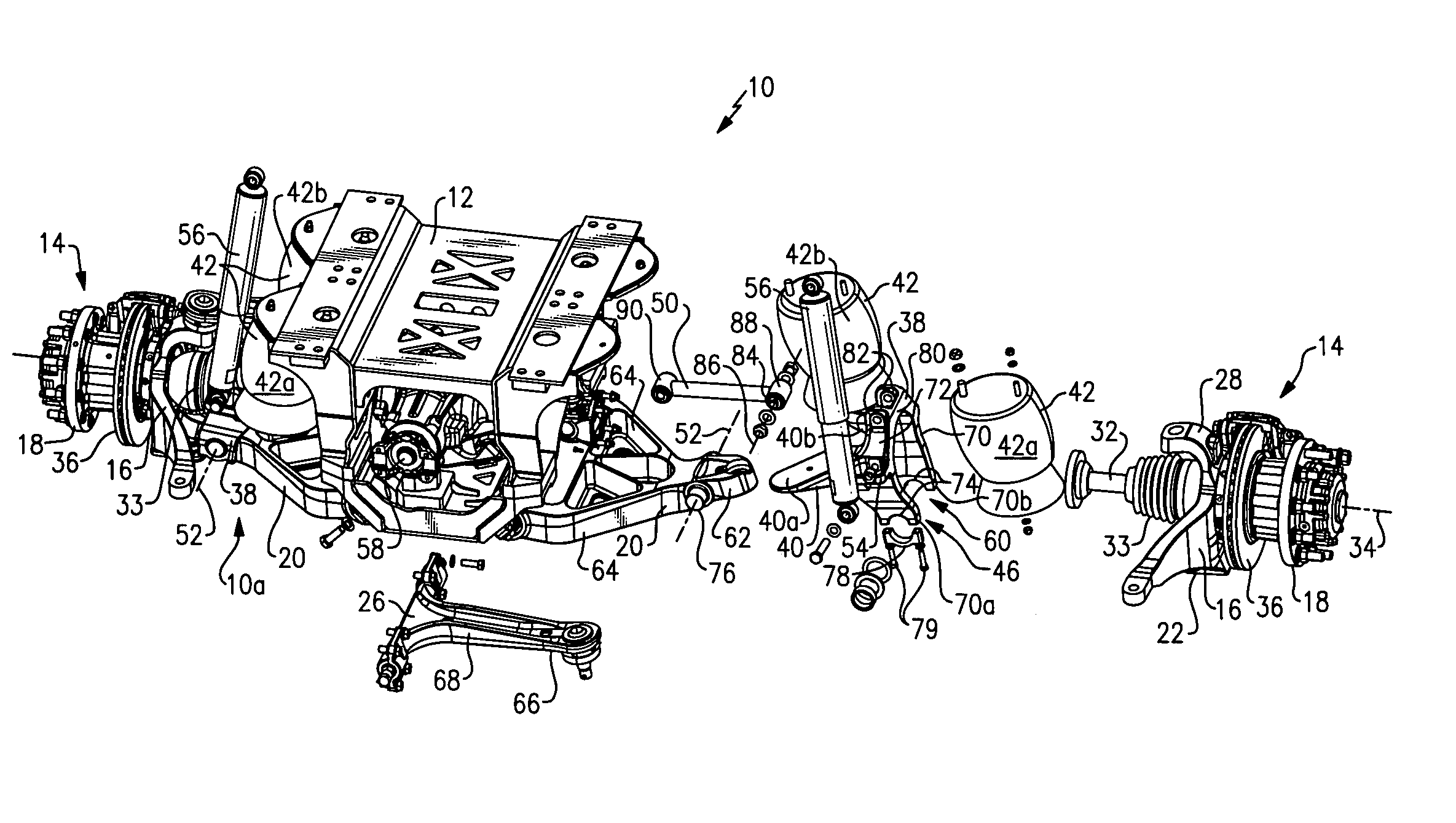
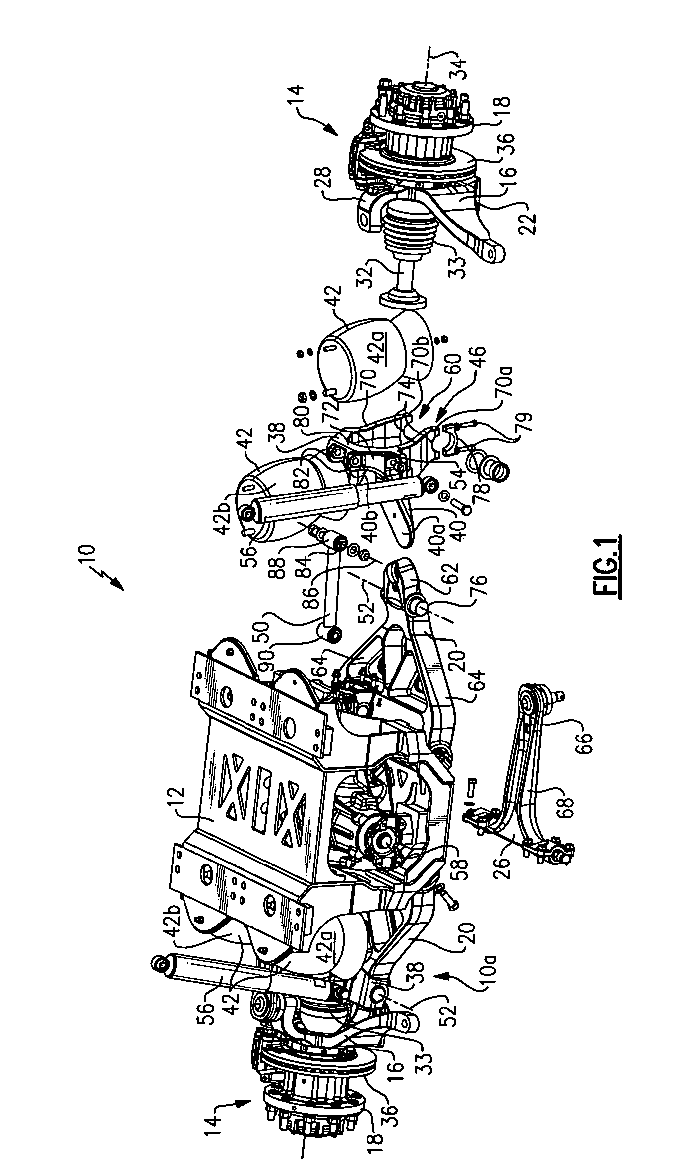
[0017]An independent suspension is shown generally at 10 in FIG. 1. The independent suspension 10 is mounted on a vehicle chassis or suspension sub-frame 12 adjacent to laterally spaced wheel assemblies 14. Each wheel assembly 14 includes a separate independent suspension unit 10a, 10b that provides for independent wheel movement at each wheel assembly 14. In one example, the independent suspension 10 is utilized on an 8×8 vehicle (not shown), however, the independent suspension 10 could be utilized on other vehicle configurations.

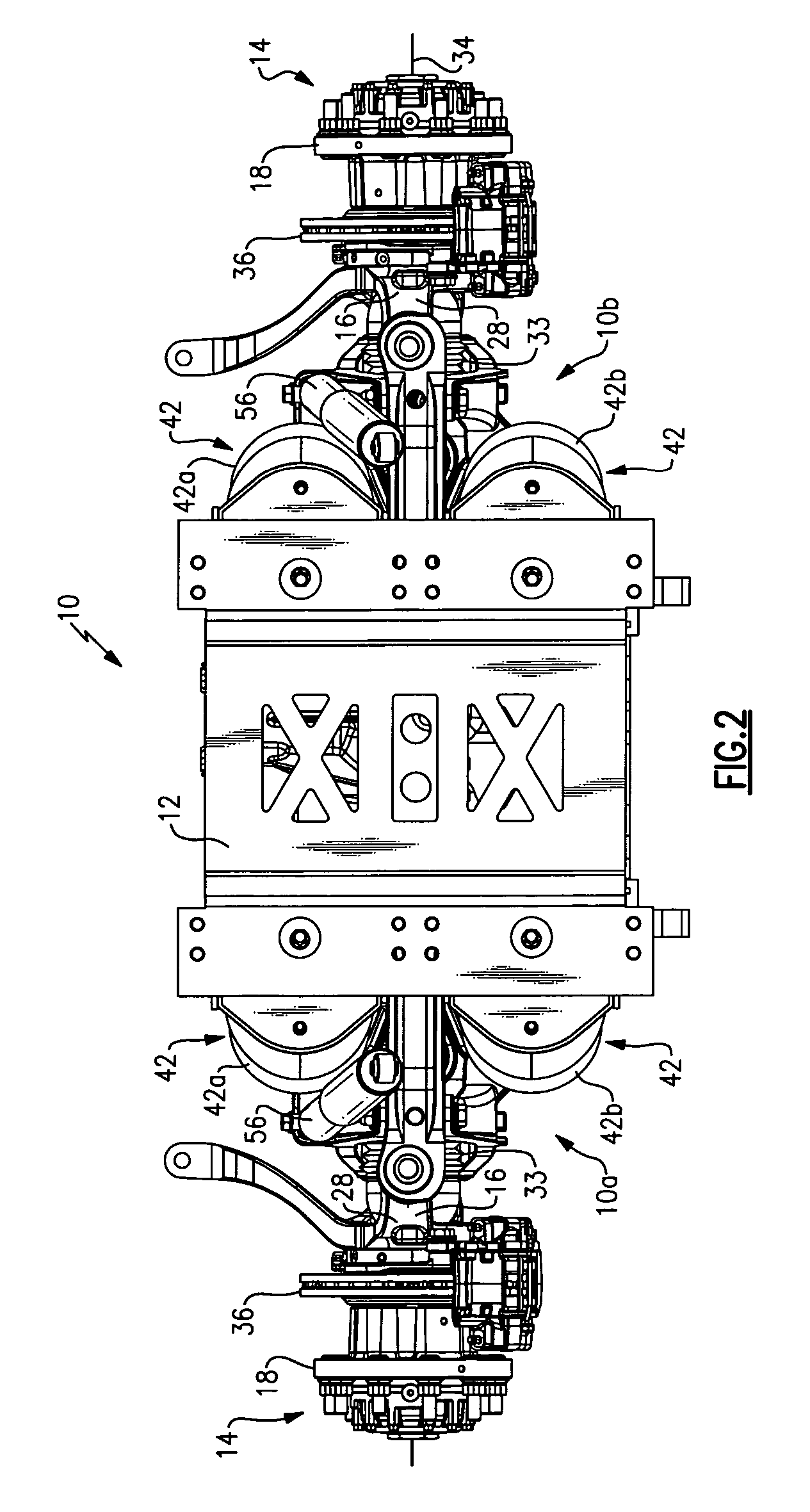
[0018]The independent suspension unit 10a for the left hand wheel assembly 14 is fully assembled, and the independent suspension unit 10b for the right hand wheel assembly 14 is shown in an exploded view. FIGS. 2-5 show different views of the independent suspension units 10a, 10b fully assembled for both wheel assemblies 14.

[0019]Each wheel assembly 14 includes a knuckle 16 having a spindle that supports a wheel hub 18. As best shown in FIG. 4, a lower con...


PUM


Abstract

An independent suspension includes upper and lower control arms that are coupled to a knuckle that supports a wheel assembly. A spring bracket is pivotally connected to the lower control arm. A drive shaft extends through an opening in the spring bracket to drive the wheel assembly. The spring bracket includes first and second support plates that respectively support first and second springs on opposite sides of the drive shaft. A torque rod is pivotally connected to the spring bracket. The torque rod and the upper and lower control arms are also mounted to a vehicle frame member. The torque rod, knuckle, spring bracket, upper and lower control arms, and vehicle structure cooperate to provide a six link control that accommodates large wheel jounce travel.

Description

RELATED APPLICATION[0001]This application claims priority to U.S. Provisional Application No. 60 / 682,893 filed on May 20, 2005.TECHNICAL FIELD[0002]This invention generally relates to a spring bracket utilized in an independent suspension for a drive axle assembly.BACKGROUND OF THE INVENTION[0003]Independent suspension systems cooperate with a drive axle assembly to allow each wheel to move vertically without affecting a laterally spaced opposite wheel. An independent suspension system is subjected to many packaging and design constraints. A central carrier assembly drives a pair of wheel drive shafts, which in turn drive a pair of wheels. Suspension components must be packaged around the central carrier assembly and the wheel drive shafts. These suspension components include upper and lower control arms, shock absorbers, and air springs, for example.[0004]It is desirable to provide a spring element, such as an air spring, at a position that is near an axle centerline in order to ac...

Claims


Application Information

Patent Timeline
Patent Type & Authority Patents(United States)
IPC IPC(8): B60G3/20
CPCB60G3/20B60G7/00B60G11/16B60G11/27B60G11/28B60G2200/144B60G2200/422B60G2200/44B60G2202/1524B60G2204/126B60G2204/128B60G2204/129B60G2204/143B60G2204/15B60G2204/19B60G2204/422B60G2206/0114B60G2300/026
Inventor ESHELMAN, EDWARD J.PAVUK, GREGORY D.WEEKS, GORDON AARON
Owner ARVINMERITOR TECH
Why Eureka
Try Eureka