Planar metal element and profile element

a metal element and profile technology, applied in the field of areal metal elements, can solve the problems of uneconomic punching out of part surfaces, unwanted weakening, and reduced stiffness of expanded metals, and achieve the effect of large widening of materials and high stiffness

Active Publication Date: 2010-10-26
PROTEKTORWERK FLORENZ MAISCH
View PDF13 Cites 7 Cited by
  • Summary
  • Abstract
  • Description
  • Claims
  • Application Information

AI Technical Summary

Benefits of technology

[0007]It is an object of the present invention to develop an areal metal element of the kind initially named such that the apertures are formed without material loss, with at the same time substantially no strains

Problems solved by technology

As a rule, such apertures are produced by punching procedures such that the parts punched out form waste.
This is disadvantageous, on the one hand, since these parts either have to be disposed of or made available for recycling.
On the other hand, a substantial disadvantage lies in the fact that the costs in the production of a corresponding section are determined to a predominant degree by the material costs.
A punching out of pa

Method used


Image

  • Planar metal element and profile element
  • Planar metal element and profile element
  • Planar metal element and profile element

Examples


Embodiment Construction

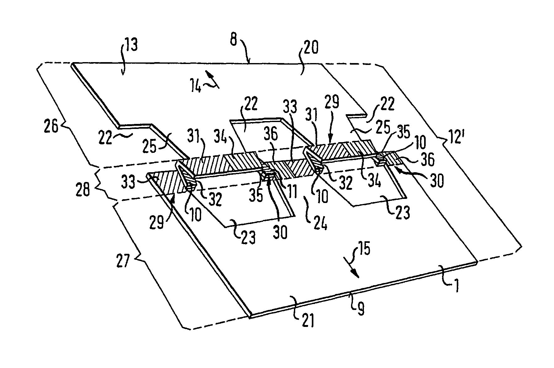
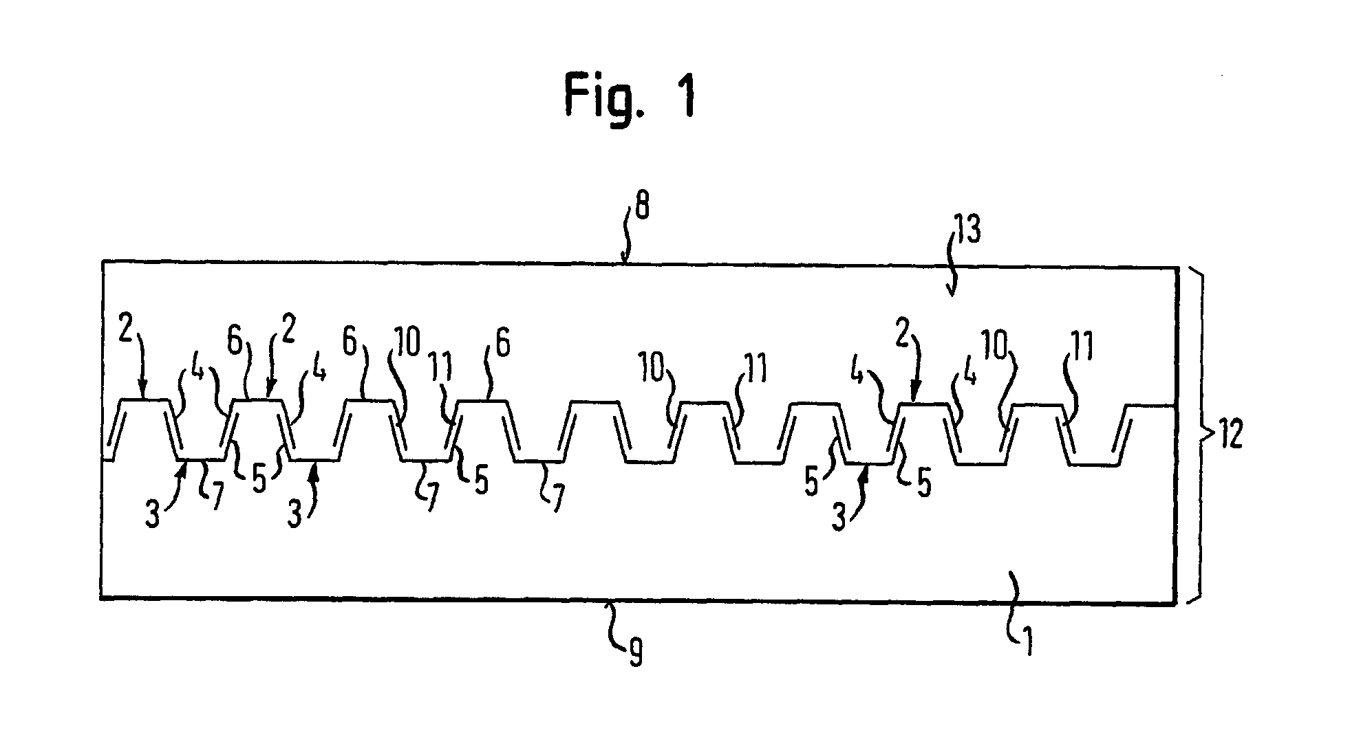
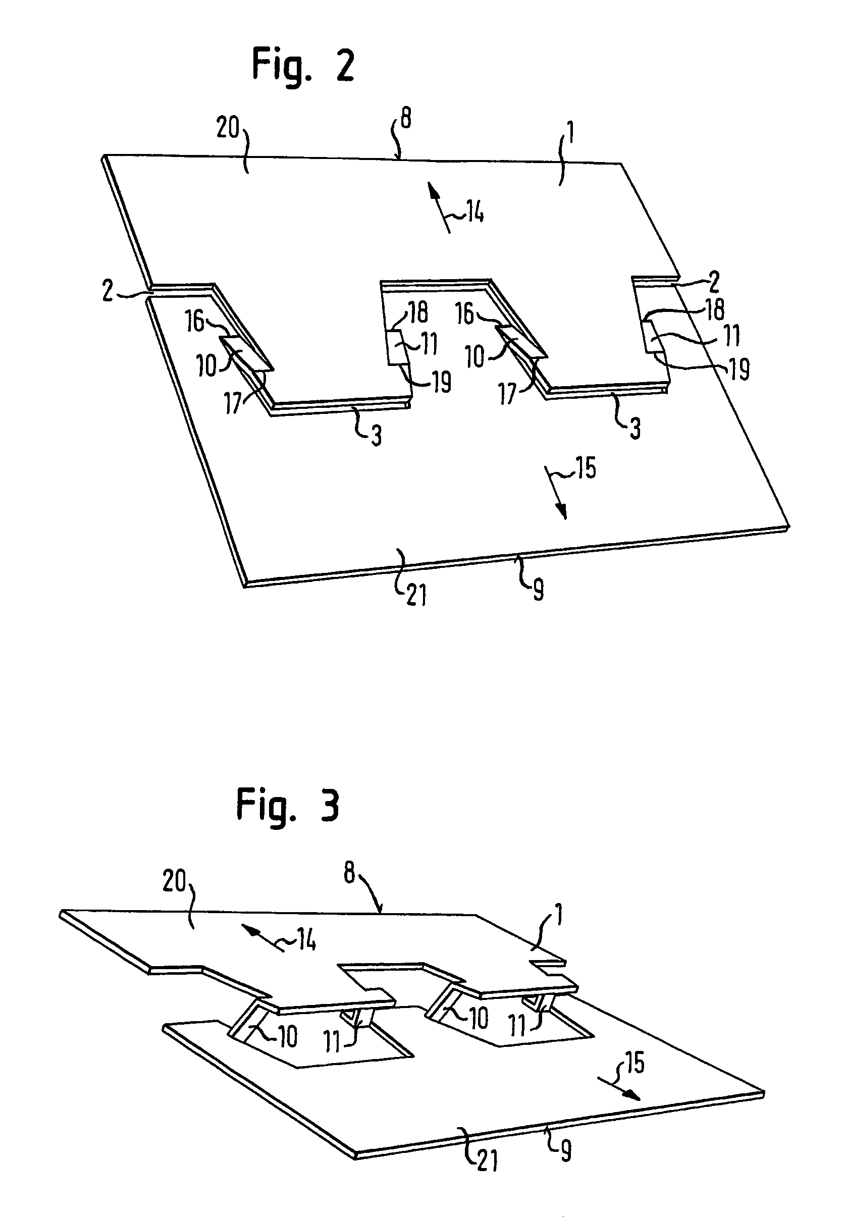
[0044]FIG. 1 shows an elongated material strip 1, in particular a metal sheet into which slots 2, 3 extending in meander shape are cut. The slots 2, 3 can be introduced into the material strip 1, for example, by a punching method or by a cutting method (e.g. a rotary cutting method, a laser cutting method) or by another suitable method.

[0045]The slots 2, 3 are each made in U shape, with the two limbs 4, 5 running apart from one another toward the open side of the U.

[0046]The limbs 4, and also the limbs 5, are each connected to one another by linear base cuts 6, 7 which are each arranged parallel to one another.

[0047]The U-shaped slots 2 each lie at the same height, following one another periodically in series along the longitudinal axis of the material strip 1. The U-shaped slots 3 along the longitudinal axis of the material strip 1 lie at equal intervals following one another in series, with the open sides of the U-shaped slots 2 and 3, however, facing toward the respectively other...


PUM

PropertyMeasurementUnit
Fractionaaaaaaaaaa
Angleaaaaaaaaaa
Angleaaaaaaaaaa

Abstract

An areal metal element is described having a surface which extends from a first outside edge to a second outside edge lying opposite the first out-side edge. The region of the metal element adjoining the first outside edge forms a first edge region and the region of the metal element adjoining the second outside edge forms a second side region. Both side regions are connected to one another by a central region lying therebetween, with at least one completely bordered aperture being formed at least in one of the side regions, with its border being formed in one part by this side region and in another part by the central region. The central region includes at least two sections which each consist of two outwardly disposed part sections and a central part section lying therebetween. The outwardly disposed part sections are folded over with respect to the central section to produce the aperture. The sections form part of the border of the aperture and the central region including the sections is made in one piece with the two side regions of the metal element.

Description

BACKGROUND OF THE INVENTION[0001]1. Field of the Invention[0002]The present relation relates to an areal metal element having a surface which extends from a first outside edge to a second outside edge lying opposite the first outside edge, with the region of the metal element adjoining the first outside edge forming a first side region and the region of the metal element adjoining the second outer edge forming a second side region, both said side regions being connected to one another by a central region lying between them, and with at least one completely bordered aperture being formed in at least one of the side regions, with its border being formed in one part by said side region and in another part by the central region. The invention is furthermore directed to a section element which is produced from such an areal metal element.[0003]2. Description of Related Art[0004]Areal metal elements of the kind initially named are used, for example, in the production of sections. Such sec...

Claims


Application Information

Patent Timeline
IPC IPC(8): E04C2/42E04C3/08E04C2/08
CPCE04C2/08E04C2/427E04C3/083Y10T428/12354Y10T29/496Y10T428/12361Y10T428/12368
Inventor KRETTENAUER, KILIAN
Owner PROTEKTORWERK FLORENZ MAISCH
Why Eureka
Try Eureka