Charging circuit

a charging circuit and circuit technology, applied in the direction of excess voltage responsive arrangements, emergency protective arrangements for limiting excess voltage/current, transportation and packaging, etc., can solve the problems of affecting charging operation, extremely high voltage supplied from the ac adaptor to the electronic equipment or other power supply circuit, and the inability of the electronic circuit to perform normal functions

Inactive Publication Date: 2010-10-26
ROHM CO LTD
View PDF6 Cites 12 Cited by
  • Summary
  • Abstract
  • Description
  • Claims
  • Application Information

AI Technical Summary

Benefits of technology

[0013]According to the embodiment, the clamp voltage is set according to the breakdown voltage of the charging control circuit, and the clamp circuit is incorporated into the charging control circuit. Therefore, the voltage adjusting circuit generates the voltage drop even if the overvoltage is applied as the power supply voltage, so that the voltage exceeding the clamp voltage can be prevented from being applied to the power supply terminal.
[0024]According to the embodiment of the invention, when the power supply voltage supplied to the power supply terminal exceeds the threshold voltage, the electric conduction is established in the path including the first switch and the first clamp circuit. As a result, the clamping is performed such that the power supply voltage becomes below the clamp voltage, and the overvoltage protection can be realized.
[0026]In this case, the generation of malfunction or trouble caused by the operation in the overvoltage state can be prevented in a part of the function of the semiconductor integrated circuit.

Problems solved by technology

When the voltage exceeding the breakdown voltage is applied, the electronic circuit cannot perform the normal function.
For example, sometimes the extremely high voltage is supplied from the AC adaptor incompatible with the electronic equipment or other power supply circuits.
When the voltage supplied from the outside exceeds the breakdown voltage of the charging circuit, not only a charging operation is affected, but also reliability is possibly affected in the charging circuit, the battery, and the electronic equipment.
On the other hand, when the user uses an external power supply incompatible with the electronic equipment, the extremely high overvoltage exceeding the breakdown voltage is possibly applied to the charging apparatus.

Method used


Image

  • Charging circuit
  • Charging circuit
  • Charging circuit

Examples


first embodiment

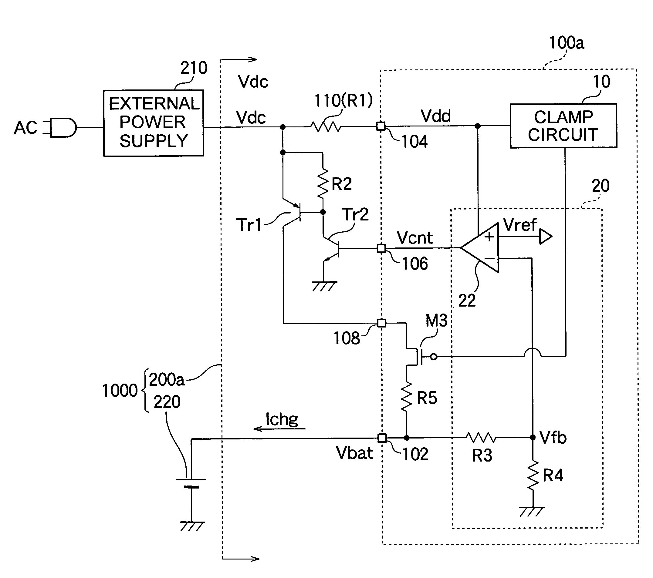
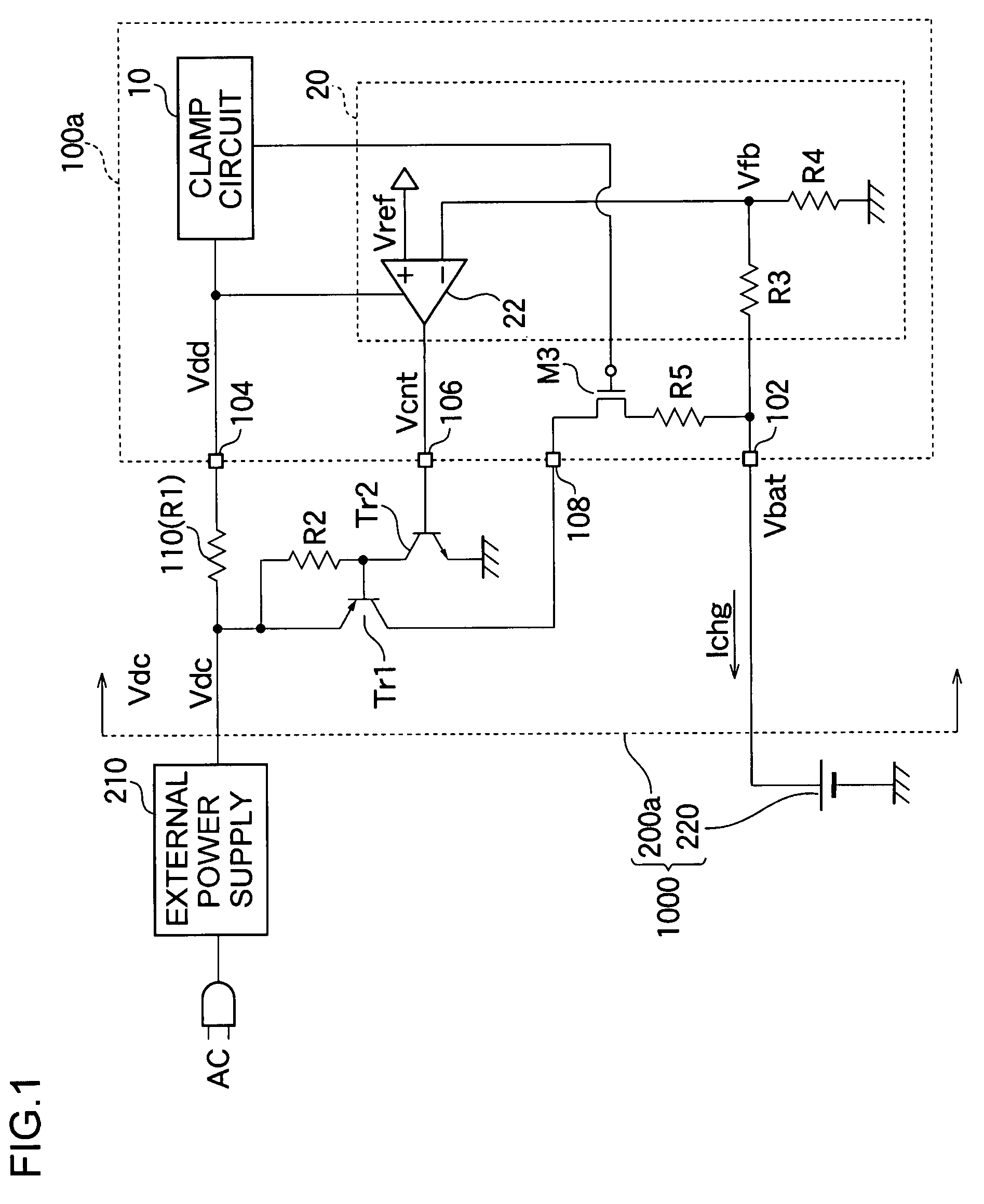
[0047]FIG. 1 is a circuit diagram showing an entire configuration of a charging circuit 200a according to a first embodiment and an electronic equipment 1000.

[0048]The electronic equipment 1000 is a battery-driven portable information terminal such as a portable telephone terminal, PDA, and a notebook PC. The electronic equipment 1000 includes the charging circuit 200a and a battery 220. The electronic equipment 1000 also includes a power supply circuit (not shown), DSP, a liquid crystal panel, and other analog and digital circuits.

[0049]The battery 220 is a secondary battery such as a lithium-ion battery and a NiCd (nickel-cadmium) battery, and a battery voltage Vbat of the battery 220 is supplied to other circuit blocks of the electronic equipment 1000.

[0050]An external power supply 210 is an AC adaptor which converts a commercial alternating voltage into a DC (direct-current) voltage or a DC / DC converter which steps down a voltage of an in-vehicle battery. The external power supp...

second embodiment

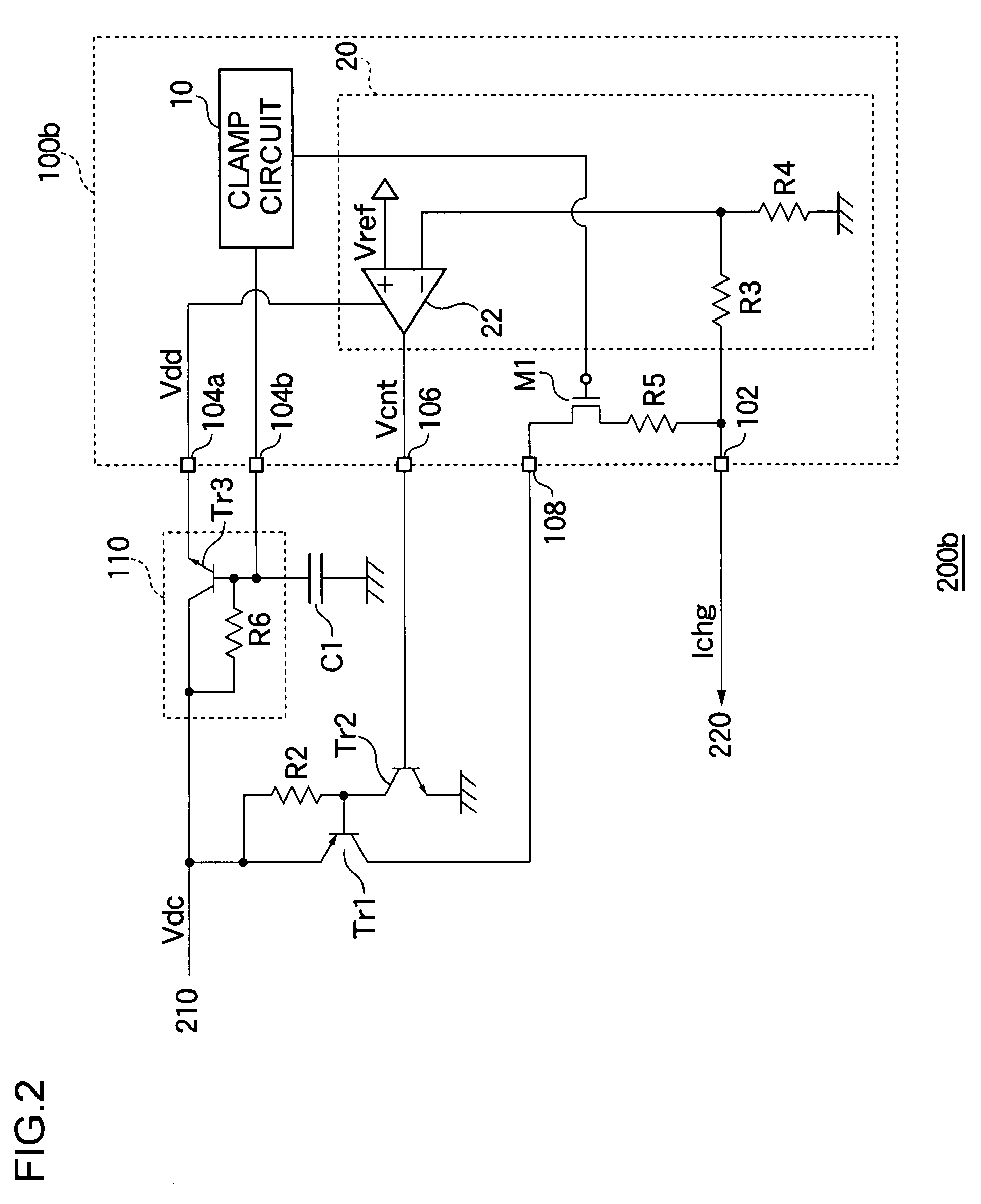
[0067]FIG. 2 is a circuit diagram showing a configuration of a charging circuit 200b according to a second embodiment. The difference between the second embodiment and the first embodiment will mainly be described.

[0068]In the charging circuit 200a of FIG. 1, a resistor element is used as the voltage adjusting circuit 110. Consequently, sometimes power consumption is increased at the voltage control resistor R1 in applying the overvoltage. For example, in the case of the external power supply voltage Vdc=30V and the clamp voltage Vclmp=7, the voltage drop of 23V is generated. When the resistance value is set to 100Ω, the power consumption of about 232 / 100≈5 W is generated. Accordingly, it is necessary that the element having the rated electric power of at least 5 W be selected as the voltage control resistor R1. From the viewpoints of size and cost of component, sometimes it is necessary to avoid the use of the resistor element having the large rated electric power. The charging cir...


PUM


Abstract

In a charging circuit charging a battery based on a power supply voltage from an external power supply, a charging transistor is provided on a path from the external power supply to the battery. A charging control circuit is integrated on a semiconductor substrate, and adjusts an ON state of the charging transistor to control a charging current supplied to the battery. The voltage adjusting circuit provided on an electric power supply path from the external power supply to a power supply terminal of the charging control circuit generates a necessary voltage drop. The current adjusting circuit adjusts the ON state of the charging transistor such that a voltage of the battery is brought close to a predetermined voltage value. The clamp circuit clamps a voltage at the power supply terminal of the charging control circuit below a predetermined clamp voltage.

Description

BACKGROUND OF THE INVENTION[0001]1. Field of the Invention[0002]The present invention relates to a charging circuit which charges a secondary battery based on an external power supply voltage, particularly to an overvoltage protection technique of the charging circuit. The present invention also relates to an overvoltage protection circuit which protects a circuit from an overvoltage.[0003]2. Description of the Related Art[0004]Recently, many electronic circuits such as CPU (Central Processing Unit) which performs digital signal processing, DSP (Digital Signal Processor), a liquid crystal panel, or other analog and digital circuits are mounted on various electronic equipments such as a portable phone, PDA (Personal Digital Assistant), and a notebook personal computer. In a battery-driven electronic equipment on which a battery is mounted as a power supply, each electronic circuit in the equipment is operated by a battery voltage from the battery.[0005]In the case where the battery i...

Claims


Application Information

Patent Timeline
Patent Type & Authority Patents(United States)
IPC IPC(8): H02J7/00
CPCH02J7/06H02J7/00714
Inventor NATE, SATORUYAMAMOTO, ISAOHORIUCHI, SACHITO
Owner ROHM CO LTD
Why Eureka
Try Eureka