Power electronics unit

a technology of power electronics and electronics, applied in the direction of power conversion systems, electronic commutation motor control, control systems, etc., can solve problems such as damage to power electronics systems

Active Publication Date: 2018-12-27
L 3 COMM MAGNET MOTOR
View PDF6 Cites 5 Cited by
  • Summary
  • Abstract
  • Description
  • Claims
  • Application Information

AI Technical Summary

Benefits of technology

[0005]It is the object of the present invention to make available an alternative and, in terms of circuit technology, simpler protection device against voltage kickback or retroactive voltages in a permanent magnet electric machine, which is designed in particular for operation of the electric machine in the field weakening mode.
[0012]In particular, the power switch may be designed as a switching component of an inverter bridge for driving the stator winding. For example, an inverter for driving an electric machine may comprise an inverter bridge, comprising two power switches each of a first and a second bridge. Each phase of the electric machine then may have a short-circuit switching circuit of its own associated therewith, which is constituted by two power switches of the first and second bridges each. The power switches in the first or second bridge branch then may be short-circuited in response to an overvoltage, for protecting the inverter from overvoltage.
[0018]It may also be provided to permit activation of the short-circuit switching circuit only in certain modes of operation of the electric machine, for example, by designing the short-circuit switching circuit such that it effects a switching of the power switch for generating a short-circuit of the associated stator winding only when the electric machine is operating in a field weakening mode. In case of a permanent magnet electric machine, the field weakening is achieved in that the phase angle of the countervoltage imparted by the power electronics system and thus the effective phase current is altered with respect to the EMF of the rotor. As a result, there is created an opposing field emanating from the stator windings, which partially displaces the exciting field generated by the permanent magnets of the rotor. In the field weakening mode, there can be achieved higher speeds than the maximum speed set by the maximum voltage carrying capacity of the electronic components in case of proportionality of speed and induced voltage, as the EMF acting in the direction of the power electronics system is lowered by the inductive voltage drop in the machine in case of current flow and the maximum admissible voltage effective at the power electronics system is applied in case of higher speeds only.
[0023]In case of a multi-phase configuration of electric machine and overvoltage protection device, it is favorable to form the short-circuit switching circuit in such a manner that it is in data exchange communication with the short-circuit switching circuit or circuits of other phases in operation, in particular all other phases in operation. In this way, a certain redundancy of the phase voltage detecting device can be achieved, which can be used for a more accurate detection of the phase voltages, e.g., by evaluating all phase voltages in cases where all phase voltages are identical. Also, the failure of one phase voltage detecting device can be detected by the other phase voltage detecting devices.

Problems solved by technology

However, this method requires protection mechanisms against sudden failure of the reactive current component, because the inductive voltage drop is not present in this case and the “unmanipulated” EMF is present at the power electronics system.
If this occurs in speed ranges where the EMF is higher than the maximum allowable value for the power electronics system, damage to the power electronics system up to partial destruction of the same may result.

Method used


Image

  • Power electronics unit
  • Power electronics unit
  • Power electronics unit

Examples


Embodiment Construction

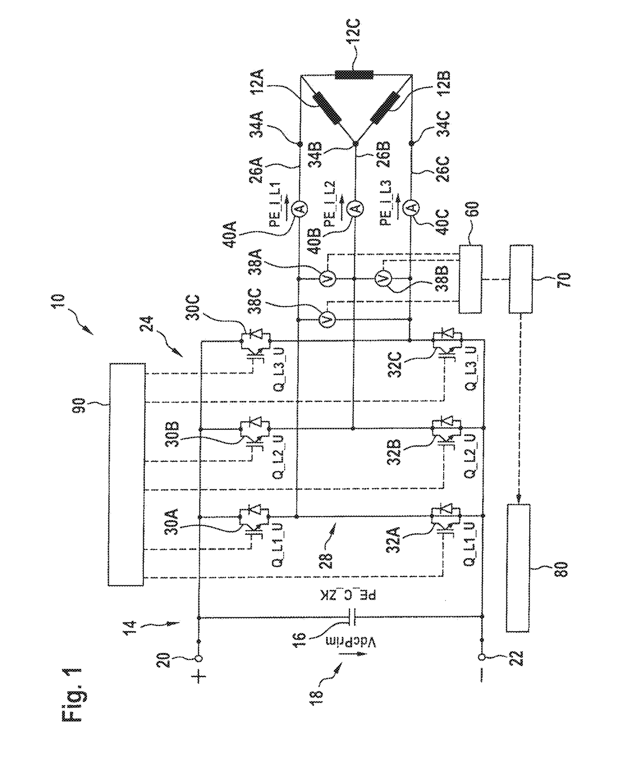
[0033]FIG. 1 shows, in schematic and simplified manner, a circuit diagram of a portion of a power electronics unit 10 for driving a permanent magnet electric machine in delta connection configuration. The electric machine comprises a stator with stator windings 12A, 12B, 12C and a rotor carrying permanent magnets (not shown in FIG. 1). In FIG. 1, only the three stator windings 12A, 12B, 12C are illustrated schematically. The power electronics unit 10 has a DC voltage intermediate circuit 14 with a capacitor 16 indicated on the left side in FIG. 1. The DC voltage intermediate circuit 14 supplies an intermediate circuit voltage VdcPrim (denoted by 18 in FIG. 1) between a positive pole 20 (indicated as a positive potential rail or bus) and a negative pole 22 (indicated as a negative potential rail or bus). The DC voltage intermediate circuit 14 feeds an inverter 24 having the stator windings 12A, 12B, 12C connected to the outputs 26A, 26B, 26C of the same. The inverter 24 comprises a t...


PUM


Abstract

A power electronics unit for driving an electric machine excited by permanent magnets and including a rotor and a stator having at least one stator winding, comprising at least one power switch designed to drive the stator winding, and an overvoltage protection device to protect the power switch from overvoltage. The overvoltage protection device comprises a phase voltage detecting device associated with the power switch as well as a short-circuit switching circuit which, when a predetermined phase voltage threshold value of the phase voltage detected by the phase voltage detection device is reached or exceeded, is adapted to be activated for short-circuiting the stator winding associated with the power switch. The short-circuit switching circuit comprises the power switch designed to drive the stator winding.

Description

BACKGROUNDTechnical Field[0001]The present invention relates to a power electronics unit for driving an electric machine excited by permanent magnets and including a rotor and a stator having at least one stator winding. The power electronics unit comprises at least one power switch designed to drive the stator winding, and an overvoltage protection device for protecting the power switch from overvoltage.Description of the Related Art[0002]The EMF of machines excited by permanent magnets, i.e., motors and / or generators, has a substantially linear course with the speed of the rotor carrying the magnets. In prior art designs, the maximum EMF is achieved at the maximum speed of the rotor. With the maximum possible phase current of the power electronics system associated with the electric machine, the in theory maximum achievable base power of the machine is thus established by the maximum torque at the upper left point of the power hyperbola and the maximum speed. However, higher speed...

Claims


Application Information

Patent Timeline
Patent Type & Authority Applications(United States)
IPC IPC(8): H02H7/09H02P29/10H02H7/122H02P6/182H02H7/08H02M1/32
CPCH02H7/09H02P29/10H02H7/1227H02P6/182H02H7/0838H02M1/32H02P29/40
Inventor EHRHART, PETERSTEFFEN, JENS
Owner L 3 COMM MAGNET MOTOR
Why Eureka
Try Eureka