
Overvoltage protection circuit

a protection circuit and overvoltage technology, applied in the direction of transistors, electrical devices, semiconductor devices, etc., can solve the problems of difficult to appropriately configure the dynamic clamp voltage, the output stage transistor may deteriorate, and the possibility of thermal destruction, so as to facilitate the configuration

Inactive Publication Date: 2010-08-03
RENESAS ELECTRONICS CORP
View PDF2 Cites 6 Cited by
  • Summary
  • Abstract
  • Description
  • Claims
  • Application Information

AI Technical Summary

Benefits of technology

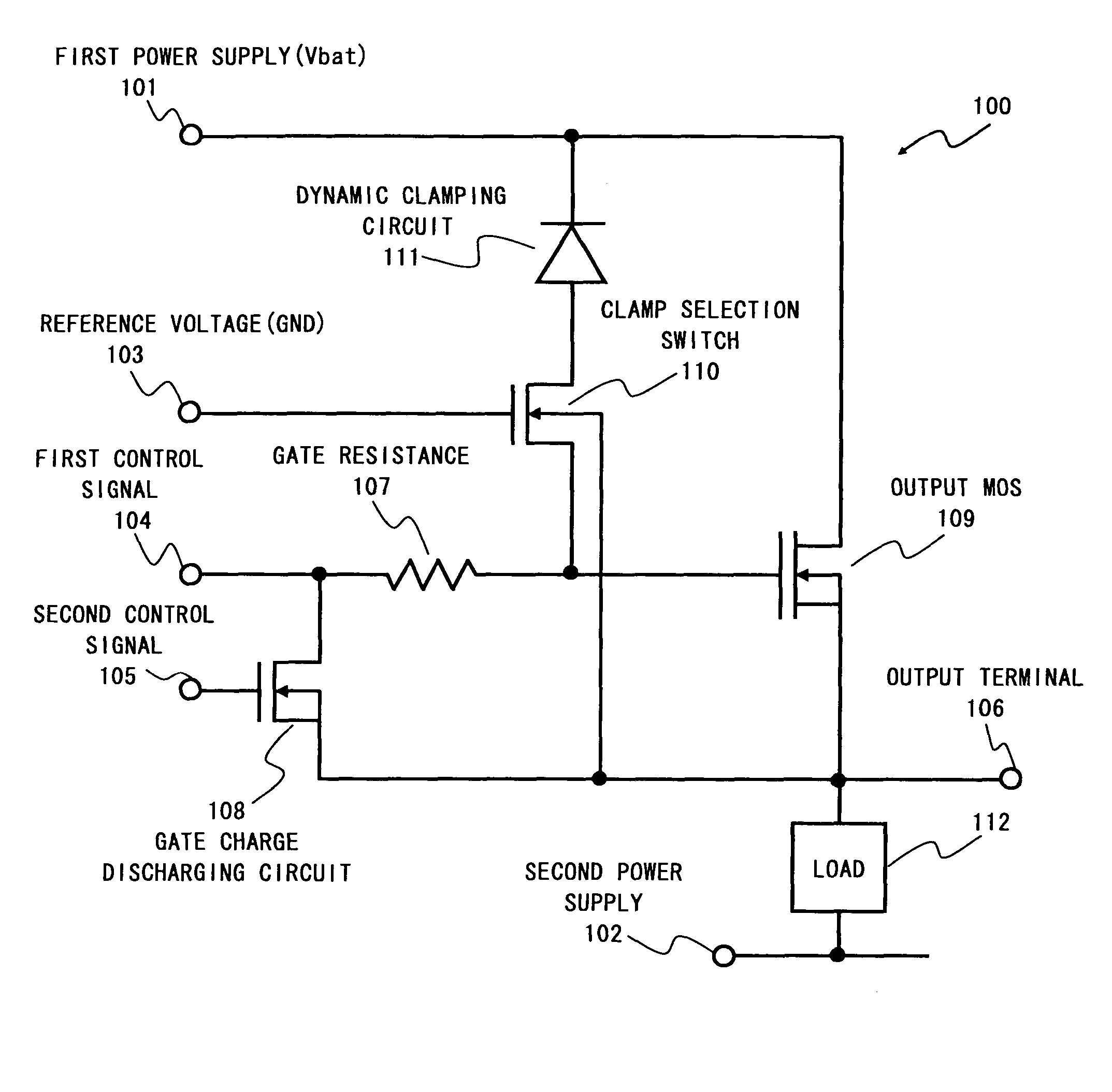
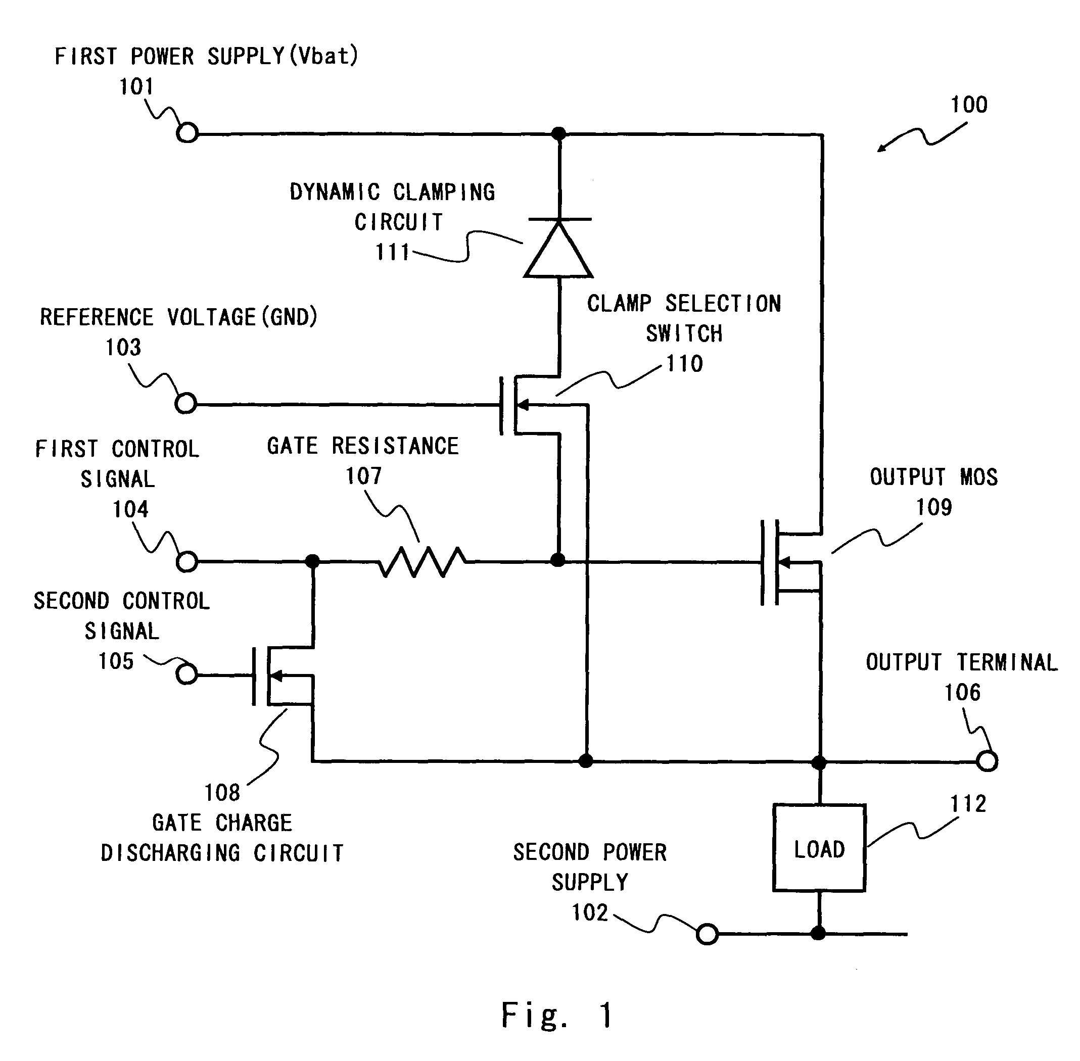
The present invention provides an overvoltage protection circuit that includes a dynamic clamping circuit and a clamp selection switch. The dynamic clamping circuit controls the voltage difference between the first power supply and the output terminal to protect the output transistor from overvoltage. The clamp selection switch becomes conductive when a negative voltage is generated in the output terminal, and the dynamic clamping circuit operates to restrict the voltage to an appropriate dynamic clamp voltage. The dynamic clamping circuit does not malfunction even if a dump surge is generated. The dynamic clamp voltage can be configured as desired, and the dynamic clamping circuit and the clamp selection switch can be realized as one device, reducing circuit area.

Problems solved by technology

An output stage transistor may deteriorate due to this breakdown current.
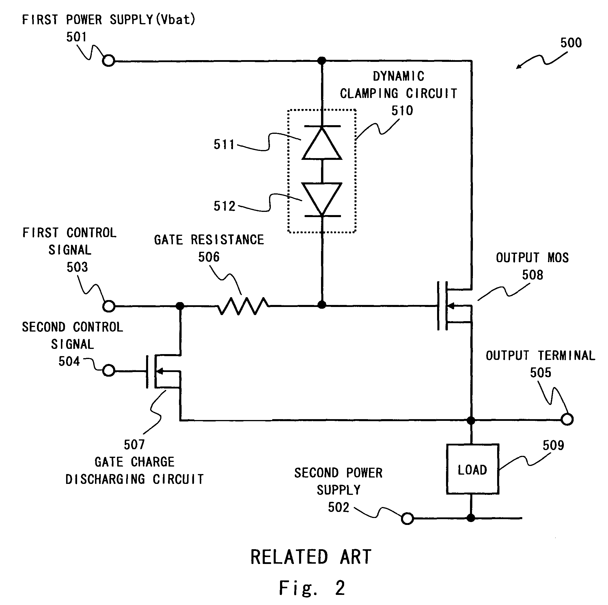
This causes a large current to flow in the output MOS transistor 508, creating possibility for thermal destruction.
However if there is no difference between the dump surge voltage and a withstand voltage of the output MOS transistor, it is difficult to appropriately configure the dynamic clamp voltage due to variations in production tolerance of the dynamic clamping circuit 510.
However even with the overvoltage protection circuit 600, if there is no difference in the absolute maximum rating and the dynamic clamp voltage, there still remains a problem in a circuit operation.
Accordingly there is a possibility that the dynamic clamping circuit 510 unintendedly operates even with a dump surge voltage lower than the absolute maximum rating, and eventually the dynamic clamping circuit 510 is destroyed by the dump surge.
There is another problem that the number of devices in a circuit increases because a logic circuit is required for the surge detection circuit 602.

Method used


Image

  • Overvoltage protection circuit
  • Overvoltage protection circuit
  • Overvoltage protection circuit

Examples


first embodiment

[0034]An overvoltage protection circuit 100 according to a first embodiment is shown in FIG. 1. As shown in FIG. 1, the overvoltage protection circuit 100 includes a gate charge discharging circuit 108, a gate resistance 107, an output MOS transistor 109, a clamp selection switch 110, a dynamic clamping circuit 111, and a load 112. A connection of the overvoltage protection circuit 100 is described hereinafter in detail.

[0035]A first terminal of the output MOS transistor 109 (for example a drain) is connected to a first power supply (for example a battery power supply) 101. A second terminal (for example a drain) is connected to a second power supply (for example a ground potential) 102. An output terminal 106 is connected to a node between the output MOS transistor 109 and the load 112. A control terminal (for example a gate) of the output MOS transistor 109 is connected to one end of the gate resistance 107. To another end of the gate resistance 107, a first control signal 104 is ...


PUM


Abstract

An overvoltage protection circuit includes an output transistor connected between a first power supply and an output terminal, a load connected to the output terminal, a dynamic clamping circuit for controlling a voltage difference between the first power supply and the output terminal, and a clamp selection switch electrically connected between the dynamic clamping circuit and the output terminal, and a conductive condition of the clamp selection switch is determined according to a comparison between a reference voltage and a voltage of the output terminal.

Description

BACKGROUND OF THE INVENTION[0001]1. Field of the Invention[0002]The present invention relates to an overvoltage protection circuit, and more particularly to an output stage MOS transistor overvoltage protection circuit for driving an inductance load.[0003]2. Description of Related Art[0004]Recently there are growing demands for increasing a withstand voltage of surge destruction for a power switch to be installed to a car. For example an inductance (L) load such as solenoid or an inductance element of wire harness is connected to an output stage of a power switch to be installed to a car. If L load is connected to an output stage of a power switch, a back electromotive force is generated on turn-off, thereby applying a negative surge voltage to an output terminal. If a voltage of the negative surge voltage exceeds the withstand voltage to destruction of an output stage transistor of a power switch, the output stage transistor breaks down and a breakdown current flows. An output stag...

Claims


Application Information

Patent Timeline
Patent Type & Authority Patents(United States)
IPC IPC(8): H02H9/00
CPCH03K17/0822
Inventor SOUMA, OSAMU
Owner RENESAS ELECTRONICS CORP
Learn More