Complex protection device

a protection device and complex technology, applied in the direction of emergency protection circuit arrangement, emergency protection arrangement for limiting excess voltage/current, electric devices, etc., can solve the problems of insufficient high-power application of protection devices, insufficient durability of protection devices, and difficulty in dealing with various environments, so as to achieve sufficient insulating distance, improve thermal characteristics, and reduce the effect of fusible element breaking tim

Active Publication Date: 2017-08-01
SMART ELECTRONICS CO LTD
View PDF14 Cites 4 Cited by
  • Summary
  • Abstract
  • Description
  • Claims
  • Application Information

AI Technical Summary

Benefits of technology

[0010]Therefore, the present invention has been made in view of the above problems, and it is an object of the present invention to provide a complex protection device in which both surface-mounted resistive elements and printed resistive elements are installed and thus a circuit and circuit elements installed on the circuit may be protected from overvoltage as well as overcurrent.
[0011]It is another object of the present invention to provide a complex protection device in which printed resistive elements are disposed under surface-mounted resistive elements and thus product miniaturization may be achieved.
[0012]It is another object of the present invention to provide a complex protection device in which surface-mounted resistive elements and printed resistive elements are mounted on a substrate without lead wires and thus an automation process may be easily applied.

Problems solved by technology

Further, since the paste-type resistor 2 is used, the protection device has weak durability insufficient to be applied for high power and is difficult to cope with various environments.

Method used


Image

  • Complex protection device
  • Complex protection device
  • Complex protection device

Examples


Embodiment Construction

[0044]Hereinafter, preferred embodiments of the present invention will be described in detail with reference to the annexed drawings.

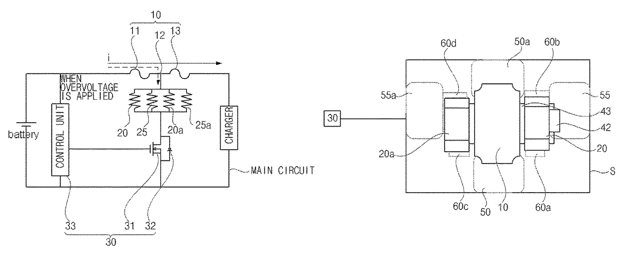
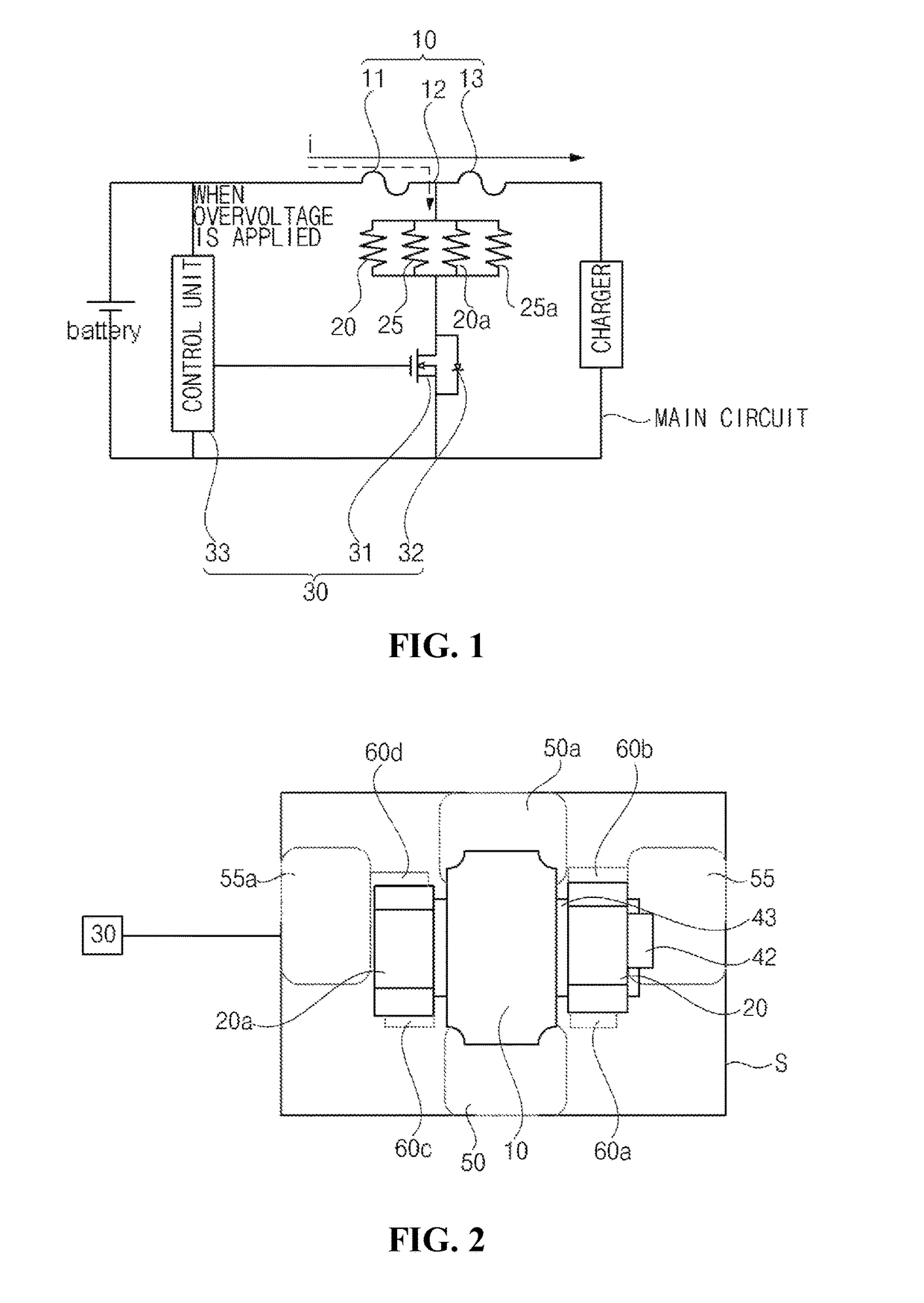
[0045]With reference to FIG. 1, a complex protection device in accordance with the present invention serves to protect elements connected to a main circuit in an abnormal state by breaking a fusible element 10 connected to the main circuit.

[0046]The main circuit to which the complex protection device in accordance with the present invention is applied is not limited in kinds and, for example, the main circuit may be a charging circuit in which charging of a battery is performed.

[0047]The fusible element 10 and a battery are connected and a charger and the fusible element 10 are connected on the main circuit.

[0048]In more detail, a plurality of resistive elements 20, 20a, 25, and 25a connected to the fusible element 10 and a switching element 30 connected to the plurality of resistive elements 20, 20a, 25, and 25a may be provided on the main circuit.

[00...


PUM


Abstract

Disclosed is a complex protection device including a substrate, fuse terminals provided on the substrate, first resistive terminals provided on the substrate so as to be separated from the fuse terminals, second resistive terminals provided on the substrate opposite to the first resistive terminals across the fuse terminals, a fusible element connected to the fuse terminals, a first surface-mounted resistive element connected to the first resistive terminals, a second surface-mounted resistive element connected to the second resistive terminals, at least one printed resistive element connected to at least one of the first resistive terminals and the second resistive terminals and connected to at least one of the first surface-mounted resistive element and the second surface-mounted resistive element, and a switching element controlling flow of current to the first and second surface-mounted resistive elements and the at least one printed resistive element if overvoltage is applied.

Description

BACKGROUND OF THE INVENTION[0001]Field of the Invention[0002]The present invention relates to a complex protection device, and more particularly to a complex protection device in which both surface-mounted resistive elements and printed resistive elements are installed and thus a circuit and circuit elements installed on the circuit may be protected from overvoltage as well as overcurrent, and the printed resistive elements are disposed under the surface-mounted resistive elements and thus product miniaturization may be achieved.[0003]Description of the Related Art[0004]A non-return type protection device, operated in response to excessive heat generated by overcurrent of a protected apparatus or ambient temperature, is operated at a designated temperature and intercepts an electrical circuit. For example, there is a protection device heating a resistor in response to signal current detecting abnormality of an apparatus and operating a fuse element using generated heat.[0005]Korean ...

Claims


Application Information

Patent Timeline
Patent Type & Authority Patents(United States)
IPC IPC(8): H01H37/04H02H9/04
CPCH02H9/044
Inventor KANG, DOO WONKIM, HYUN CHANGKIM, KWANG BEOMYUN, SAENG SOOKWON, HYUK JAE
Owner SMART ELECTRONICS CO LTD
Why Eureka
Try Eureka