Impulse lightning arresters and pulse arrester columns for power lines

a technology of pulse arrester and lightning arrester, which is applied in the direction of resistors, emergency protective arrangements for limiting excess voltage/current, and non-adjustable resistors, etc., can solve the problems of failure of all spark units, failure of electric installations protected by such arresters or assemblies, and difficulty in ensuring the desired low level of overvoltage limitation

Inactive Publication Date: 2005-06-28
OTKRYTOE AKTSIONERNOE OBSHCHESTVO RIF
View PDF6 Cites 3 Cited by
  • Summary
  • Abstract
  • Description
  • Claims
  • Application Information

AI Technical Summary

Benefits of technology

[0012]It is a principal object of the present invention to provide a reliable lightning arrester for protecting high-voltage installations against lightning overvoltage.

Problems solved by technology

Arresters comprising a chain of spark units and arrester assemblies provide a long flashover path; therefore their use prevents lightning flashover from developing into a power arc, so that the electric installation protected by such arrester or such assembly continues uninterrupted operation.
As a result, the arrester's discharge voltage is on the whole much higher than that of one individual spark unit, and for that reason it is often difficult to ensure a desired low level of overvoltage limitation.
Surge voltage is very unevenly distributed over such a chain, which results in a cascade break-down of all the spark units, with a sequential break-down of each of discharge gaps of the individual units.
As a consequence, the voltage—time characteristic of the prior art arrester in the domain of fast response times (about 1 μs) is quite steep, and this prevents the use of said arrester for protection of facilities with a flat voltage—time characteristic, such as cable links or transformers, when they are exposed to steep overvoltage impulses, since the arrester's response time is long enough for the impact overvoltage to grow to values dangerous to the insulation of the protected facility.
However, at 50 Hz frequency, the resistances of the additional capacitances C are rather large, so they do not have a notable effect on the voltage distribution over the spark units.

Method used


Image

  • Impulse lightning arresters and pulse arrester columns for power lines
  • Impulse lightning arresters and pulse arrester columns for power lines
  • Impulse lightning arresters and pulse arrester columns for power lines

Examples


Embodiment Construction

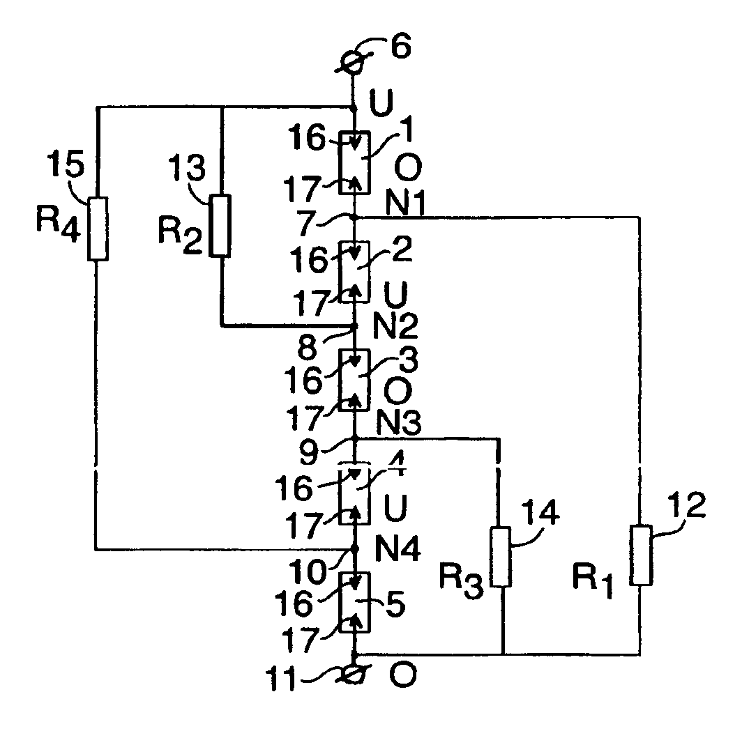
[0033]FIG. 1 presents a scheme of electrical connections for an impulse lightning arrester comprising a chain of N (N=5) spark units N1 to N5. To facilitate understanding, each spark unit is shown as comprising only one spark gap, the gaps being designated as 1′ to 5′. A first clamp 6, so-called “potential clamp” is connected to the input of the first spark unit N1 and serves to connect the arrester (either directly, or via an intermediate component, such as another arrester) to a component (such as a power line conductor) of a power transmission line subjected to a high electrical potential U. The spark units N1-N5 are connected in series, i.e. the output of each of the spark units N1-N4 is connected to the input of the next spark unit N2 to N5, respectively, at an appropriate point (these connection points being designated as 7 to 10). A second, or “ground” clamp 11 of the arrester connected to the output of the last spark unit N5, i.e. to the second electrode of this unit, serves...


PUM


Abstract

The inventive spark arrester comprises an odd number of series-connected spark units forming a chain, with each spark units comprising at least one discharge gap. In order to increase the reliability of protection of electric installation components having a flat voltage—time characteristic by ensuring a low discharge level and a fast response of the arrester, the output of each even spark unit is connected via a resistor to a clamp connecting the arrester to the protected components subjected to a high potential, while the output of each odd spark unit, except the last one, is connected via another resistor to another clamp connecting the arrester to the protected components subjected to a low potential. Preferred embodiments of the arrester promote a generation of a long surface discharge along a surface of tubular body made of a solid dielectric, said body being common for all spark units constituting the arrester. Arresters comprising several tubular bodies and arrester assemblies made of several arresters are also disclosed.

Description

REFERENCE TO PRIOR APPLICATION[0001]Thus application is entitled to the benefit of and incorporates by reference essential subject matter disclosed in PCT patent application No. PCT / RU01 / 00258 filed on 26 Jun. 2001 and Russian Application No. 2000116337 filed 27 Jun. 2000.FIELD OF INVENTION[0002]The present invention relates to the field of high-voltage techniques, more precisely, to impulse lightning arresters for protecting components of power transmission lines and high-voltage installations against overvoltages during a thunderstorm, said arresters consisting of series-connected spark gaps assembled into a chain of N (N=odd number equal to or eater than 3) series-connected spark units (or modules). The invention also relates to arrester assemblies (or columns) consisting of several arresters of the described type.BACKGROUND OF THE INVENTION[0003]Widely used prior art spark lightning arresters comprise a plurality of spark gaps (also called discharge gaps), each gap consisting of...

Claims


Application Information

Patent Timeline
Patent Type & Authority Patents(United States)
IPC IPC(8): H01C7/12H01T23/00H01T4/16H01T4/00
CPCH01C7/12H01T23/00H01T4/16H02H9/06
Inventor PILSCHIKOV, VLADIMIR YEVSEEVICHPODPORKIN, GEORGY VICTOROVICHSIVAEV, ALEXANDER DMITRIEVICH
Owner OTKRYTOE AKTSIONERNOE OBSHCHESTVO RIF
Why Eureka
Try Eureka