Method and device for reconstructing a three-dimensional fluorescence optical tomography image by double measurement

a fluorescence optical tomography and image reconstruction technology, applied in the field of three-dimensional fluorescence optical tomography image reconstruction, can solve problems such as loss of image reconstruction precision, and achieve the effect of improving reconstruction resolution

Active Publication Date: 2010-10-26
COMMISSARIAT A LENERGIE ATOMIQUE ET AUX ENERGIES ALTERNATIVES
View PDF10 Cites 24 Cited by
  • Summary
  • Abstract
  • Description
  • Claims
  • Application Information

AI Technical Summary

Benefits of technology

[0020]The object of the invention is to remedy these shortcomings, and in particular to improve the resolution of reconstruction of a three-dimensional image of the distribution of fluorophores in a diffusing medium having the form of a plate.

Problems solved by technology

As the object presents a certain thickness, the fluorophores are not all at the same distance either from the light source or from the detectors, which leads to a loss of precision in the image reconstruction.

Method used


Image

  • Method and device for reconstructing a three-dimensional fluorescence optical tomography image by double measurement
  • Method and device for reconstructing a three-dimensional fluorescence optical tomography image by double measurement
  • Method and device for reconstructing a three-dimensional fluorescence optical tomography image by double measurement

Examples


Embodiment Construction

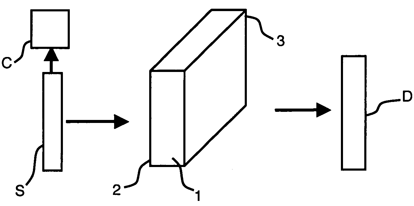
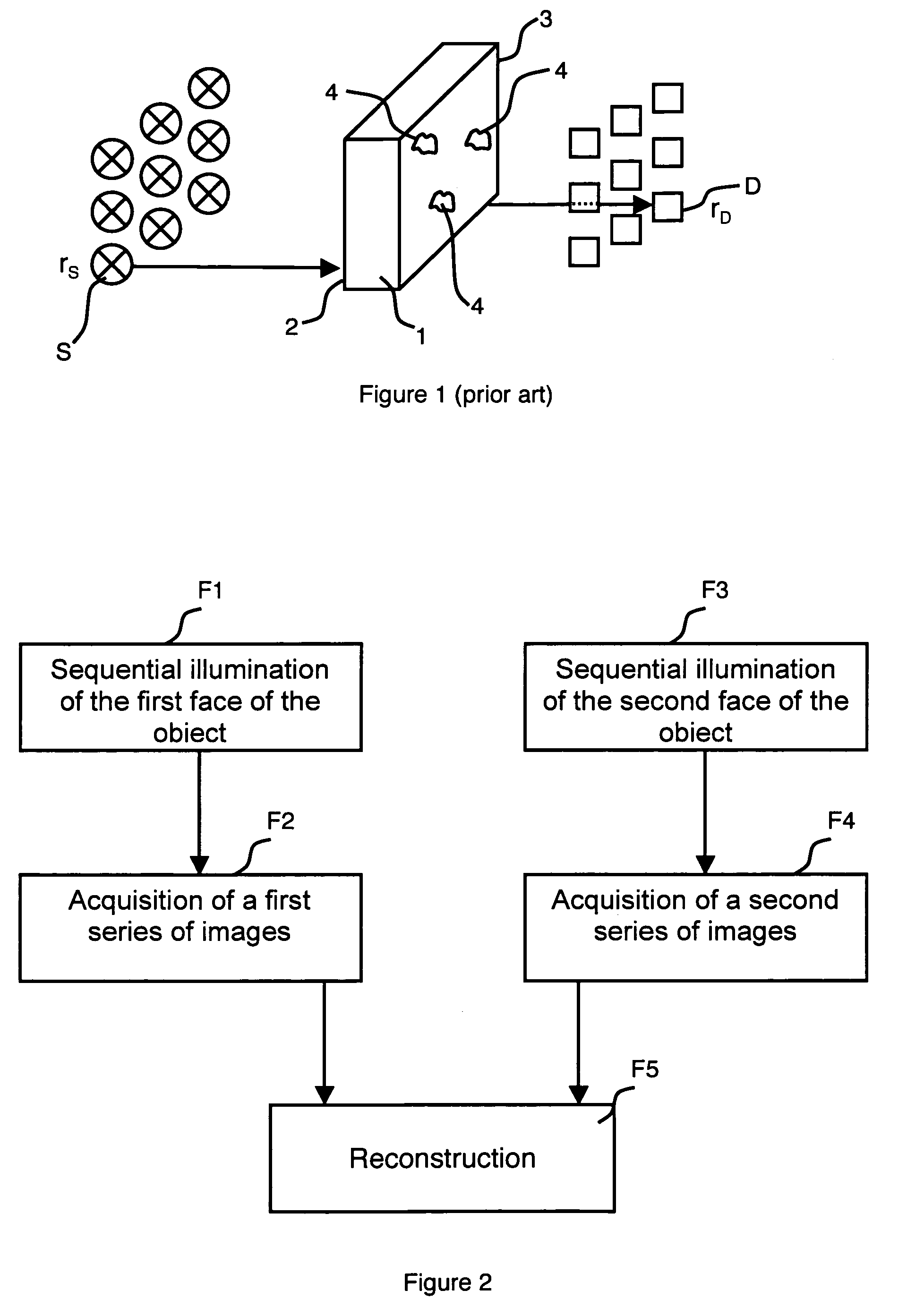
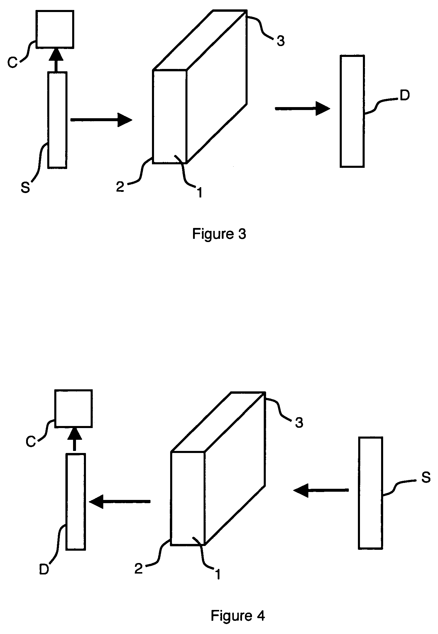
[0030]The invention relates to a parallel planes geometry, the object 1 typically having a thickness comprised between 10 and 15 mm. A set of light sources S constituting a series of discrete lighting points for illumination of the object is preferably formed by a laser source which is moved in a plane parallel to the object in two orthogonal directions in order to grid object 1. The laser typically describes a grid of 11 by 15 positions with a pitch of 3 mm in this plane. Depending on the precision to be obtained, the pitch can be reduced and, depending on the size of the zone to be observed, the number of points can be increased (for example about 30 points or more in both directions).

[0031]The set of detectors is preferably formed by a CCD camera coupled with a lens to detect an image of the object in a plane parallel to the surface of object 1. The camera thereby acquires one image for each position of the laser source. More precisely, when the object is sequentially illuminated...


PUM

PropertyMeasurementUnit
heightaaaaaaaaaa
thicknessaaaaaaaaaa
thicknessaaaaaaaaaa

Abstract

To examine a plate-shaped object comprising fluorophores and having a first face and an opposite second face, the method comprises a first sequential illumination step of the first face of the object with a fluorophore excitation light and a first sequential acquisition step of a first series of images by detecting light emitted by the second face of the object. The density of the lighting points is lower than the density of the detection points and the method further comprises a second sequential illumination step of the second face of the object with a fluorophore excitation light and a second sequential acquisition step of a second series of images by detecting light emitted by the first face of the object. Reconstruction of the three-dimensional fluorophore distribution image in the object is performed by means of the first and second series of images.

Description

BACKGROUND OF THE INVENTION[0001]The invention relates to a method for reconstructing a three-dimensional fluorescence optical tomography image to examine a plate-shaped object having a first face and an opposite second face and comprising fluorophores, said method comprising:[0002]a first illumination step for a sequential illumination of the first face of the object with a fluorophore excitation light from a plurality of lighting points, the first illumination step comprising a succession of illumination phases from a lighting point associated with each phase, and[0003]a first acquisition step for a sequential acquisition of a first series of images, an image of said series being formed, at each illumination phase of the first face, by a detector comprising a plurality of detection points simultaneously detecting light emitted by the second face of the object.STATE OF THE ART[0004]Fluorescence diffuse optical tomography (fDOT) consists in determining the three-dimensional distribu...

Claims


Application Information

Patent Timeline
Patent Type & Authority Patents(United States)
IPC IPC(8): G01N21/25
CPCA61B5/0073A61B5/0091
Inventor KOENIG, ANNEHERVE, LIONEL
Owner COMMISSARIAT A LENERGIE ATOMIQUE ET AUX ENERGIES ALTERNATIVES
Why Eureka
Try Eureka