Photographing optical lens assembly

a technology of optical lens and lens assembly, which is applied in the field of can solve the problems of difficult to fit three lenses in the limited space, reduced thickness of lenses, and less space available, and achieve the effects of improving the resolution of the photographing optical lens assembly, effective correction, and shortening the focal length of the optical system

Active Publication Date: 2010-10-26
LARGAN PRECISION
View PDF3 Cites 57 Cited by
  • Summary
  • Abstract
  • Description
  • Claims
  • Application Information

AI Technical Summary

Benefits of technology

[0007]In order to obtain good image quality, effectively reduce the total track length of the lens assembly, maintain the miniaturization of the lens assembly and reduce the sensitivity of the optical system, the present invention provides a photographing optical lens assembly comprising two lens elements and an aperture stop.
[0008]A photographing optical lens assembly comprises, in order from the object side to the image side: a first lens element with positive refractive power having a convex object-side surface and a concave image-side surface, the object-side and image-side surfaces thereof being aspheric; a second lens element with negative refractive power having a concave object-side surface and a convex image-side surface, the object-side and image-side surfaces thereof being aspheric; and an aperture stop located in front of the first lens element. In the present photographing optical lens assembly, there are exactly two lens elements with refractive power. Such an arrangement of optical elements can effectively improve the image quality of the optical system, reduce the sensitivity of the optical system and maintain miniaturization of the lens assembly.
[0009]In the present photographing optical lens assembly, the first lens element is a meniscus lens element having a convex object-side surface and a concave image-side surface so that the astigmatism of the optical system may be better corrected, and the refractive power (of each lens element) of the optical system may be distributed more appropriately to reduce the sensitivity of the optical system; the second lens element with negative refractive power enables the principal point of the optical system to be positioned far away from the image plane, thereby the total track length of the optical system may be reduced to maintain the miniaturization of the lens assembly.

Problems solved by technology

However, when the volume of the lens assembly is reduced, less space is available for the image forming system, making it difficult to fit the three lenses in the limited space.
Therefore, the thickness of the lenses must be reduced, resulting in plastic-injection-molded lenses which have poor material homogeneity.
Therefore, it may be difficult to control the yield of the lens assembly.

Method used


Image

  • Photographing optical lens assembly
  • Photographing optical lens assembly
  • Photographing optical lens assembly

Examples


first embodiment

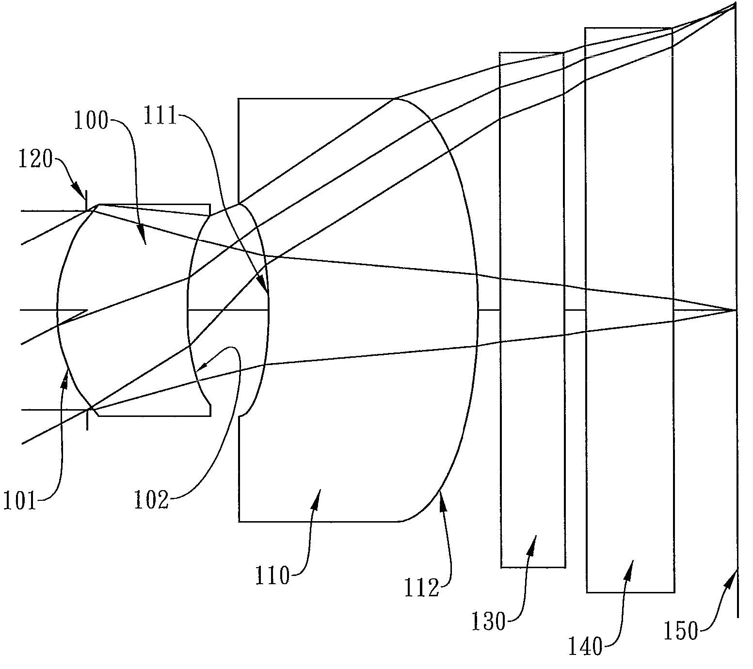
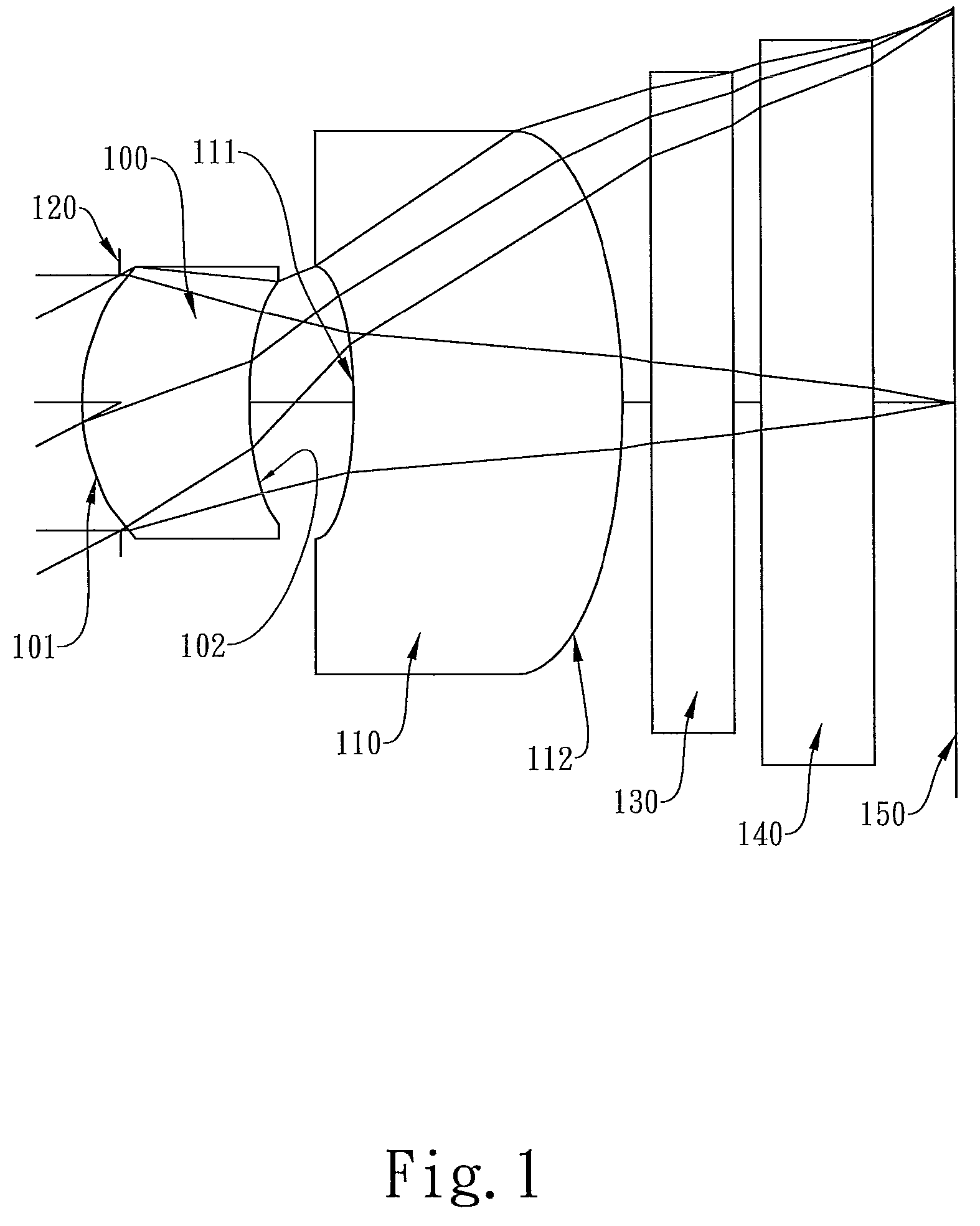
[0057]In the present photographing optical lens assembly, the focal length of the photographing optical lens assembly is f, the focal length of the first lens element 100 is f1, the focal length of the second lens element 110 is f2, and they satisfy the relations: f=2.69 mm, f / f1=1.20, f / f2=−0.04.

[0058]In the first embodiment of the present photographing optical lens assembly, the radius of curvature of the object-side surface 101 of the first lens element 100 is R1, the radius of curvature of the image-side surface 102 of the first lens element 100 is R2, the radius of curvature of the object-side surface 111 of the second lens element 110 is R3, the radius of curvature of the image-side surface 112 of the second lens element 110 is R4, and they satisfy the relations: R1 / R2=0.55, R3 / R4=0.81.

[0059]In the first embodiment of the present photographing optical lens assembly, the refractive index of the first lens element 100 is N1, and it satisfies the relation: N1=1.543.

[0060]In the f...

second embodiment

[0067]In the present photographing optical lens assembly, the focal length of the photographing optical lens assembly is f, the focal length of the first lens element 300 is f1, the focal length of the second lens element 310 is f2, and they satisfy the relations: f=4.17 mm, f / f1=1.19, f / f2=−0.34.

[0068]In the second embodiment of the present photographing optical lens assembly, the radius of curvature of the object-side surface 301 of the first lens element 300 is R1, the radius of curvature of the image-side surface 302 of the first lens element 300 is R2, the radius of curvature of the object-side surface 311 of the second lens element 310 is R3, the radius of curvature of the image-side surface 312 of the second lens element 310 is R4, and they satisfy the relations: R1 / R2=0.49, R3 / R4=0.21.

[0069]In the second embodiment of the present photographing optical lens assembly, the refractive index of the first lens element 300 is N1, and it satisfies the relation: N1=1.543.

[0070]In the...

third embodiment

[0077]In the present photographing optical lens assembly, the focal length of the photographing optical lens assembly is f, the focal length of the first lens element 500 is f1, the focal length of the second lens element 510 is f2, and they satisfy the relations: f=3.53 mm, f / f1=1.17, f / f2=−0.12.

[0078]In the third embodiment of the present photographing optical lens assembly, the radius of curvature of the object-side surface 501 of the first lens element 500 is R1, the radius of curvature of the image-side surface 502 of the first lens element 500 is R2, the radius of curvature of the object-side surface 511 of the second lens element 510 is R3, the radius of curvature of the image-side surface 512 of the second lens element 510 is R4, and they satisfy the relations: R1 / R2=0.56, R3 / R4=0.66.

[0079]In the third embodiment of the present photographing optical lens assembly, the refractive index of the first lens element 500 is N1, and it satisfies the relation: N1=1.544.

[0080]In the t...


PUM


Abstract

The present invention provides a photographing optical lens assembly comprising, in order from the object side to the image side: a first lens element with positive refractive power having a convex object-side surface and a concave image-side surface, the object-side and image-side surfaces thereof being aspheric; a second lens element with negative refractive power having a concave object-side surface and a convex image-side surface, the object-side and image-side surfaces thereof being aspheric; and an aperture stop located in front of the first lens element; wherein an Abbe number of the first lens element is V1, an Abbe number of the second lens element is V2, and they satisfy the relation: |V1−V2|<15; and wherein the number of the lens elements of the photographing optical lens assembly is limited to two. Such an arrangement of optical elements can effectively reduce the volume of the lens assembly and the sensitivity of the optical system and enable the lens assembly to obtain a higher resolution.

Description

BACKGROUND OF THE INVENTION[0001]1. Field of the Invention[0002]The present invention relates to a photographing optical lens assembly, and more particularly, to a compact photographing optical lens assembly used in a camera mobile phone.[0003]2. Description of the Prior Art[0004]In recent years, with the popularity of camera mobile phones, the demand for compact photographing lenses is increasing, and the sensor of a general photographing camera is none other than CCD (charge coupled device) or CMOS device (Complementary Metal Oxide Semiconductor device). Furthermore, as advanced semiconductor manufacturing technology has allowed the pixel size of sensors to be reduced and electronic devices have become more compact and powerful, there is an increasing demand for compact photographing lenses featuring better image quality.[0005]In order to correct aberrations, a conventional mobile phone lens assembly usually takes the form of a triplet lens design, with the most commonly seen trip...

Claims


Application Information

Patent Timeline
Patent Type & Authority Patents(United States)
IPC IPC(8): G02B3/02G02B13/18
CPCG02B13/12G02B13/18G02B27/0025
Inventor TANG, HSIANG-CHITSAI, TSUNG-HAN
Owner LARGAN PRECISION
Why Eureka
Try Eureka