Acquisition and tracking of burst code signals

a burst code and signal acquisition technology, applied in the field of signal correlation, can solve problems such as too long time period to be practical, and achieve the effect of reducing acquisition tim

Active Publication Date: 2010-10-26
L3 TECH INC
View PDF31 Cites 7 Cited by
  • Summary
  • Abstract
  • Description
  • Claims
  • Application Information

AI Technical Summary

Benefits of technology

[0010]The present invention effectively slaves the PN chipping rate clock of each platform with a timing signal for initial acquisition of the code timing. In at least one embodiment, the timing signal is derived from the Global Positioning System (GPS). The relative phase between the timing signal and the spreading code is then maintained such that the code timing uncertainty falls within a parallel correlator window. Thus, the present invention makes it possible to acquire the code timing of a digital communication system by using a timing signal such as those provided by the GPS system, and a spreading code relative-phase computation method to effectively slave the chipping rate clocks of each platform to the timing signal. The mean time to re-acquire the code timing for each subsequent burst is significantly decreased by simultaneously correlating the received burst code signal over the uncertainty window of relative code phases of the locally generated de-spreading code. The size of the uncertainty window is reduced with the above mentioned timing signal-PN code slaving method. Thus, digital communication platforms are effectively synchronized to a timing signal, allowing initial PN code acquisition, tracking, and burst code signal re-acquisition to be accomplished in a physical system.
[0011]A detect / dismissal algorithm utilized by this technique is assumed to be a fixed-time method, i.e., the correlation is observed for a fixed time and then a detect or dismiss decision is made, so that an easy comparison to the conventional single channel user can be developed.
[0012]The purpose of the circuitry and techniques described herein is to decrease the mean time to code timing acquisition of a burst of data in a digital communication system, allowing the acquisition portion of the data block to be shorter, thereby increasing the system throughput. The code timing information is then passed to legacy circuitry that performs chip-by-chip dc-spreading, symbol rate matched filtering, time tracking, and carrier tracking.
[0014]In another embodiment a digital communication system includes a generator for generating a plurality of pulse trains, each having a different timing, and pre-compensation circuitry for synchronizing the plurality of pulse trains to a timing signal. The digital communication system also includes comparison circuitry for simultaneously comparing a received burst code signal to each of the plurality of pulse trains, where the received burst code signal is synchronized to the timing signal. The digital communication system further includes a detector for detecting which of the pulse trains is a closest temporal match to the received burst code signal. The pre-compensation circuitry operates to reduce acquisition time and keep PN code uncertainties within the range of the comparison circuitry.

Problems solved by technology

Known acquisition techniques may achieve detection after receiving the code pattern approximately five times. Utilizing this type of generator requires approximately five days to attain acquisition, a time period that is too long to be practical.

Method used


Image

  • Acquisition and tracking of burst code signals
  • Acquisition and tracking of burst code signals
  • Acquisition and tracking of burst code signals

Examples


Embodiment Construction

(s)

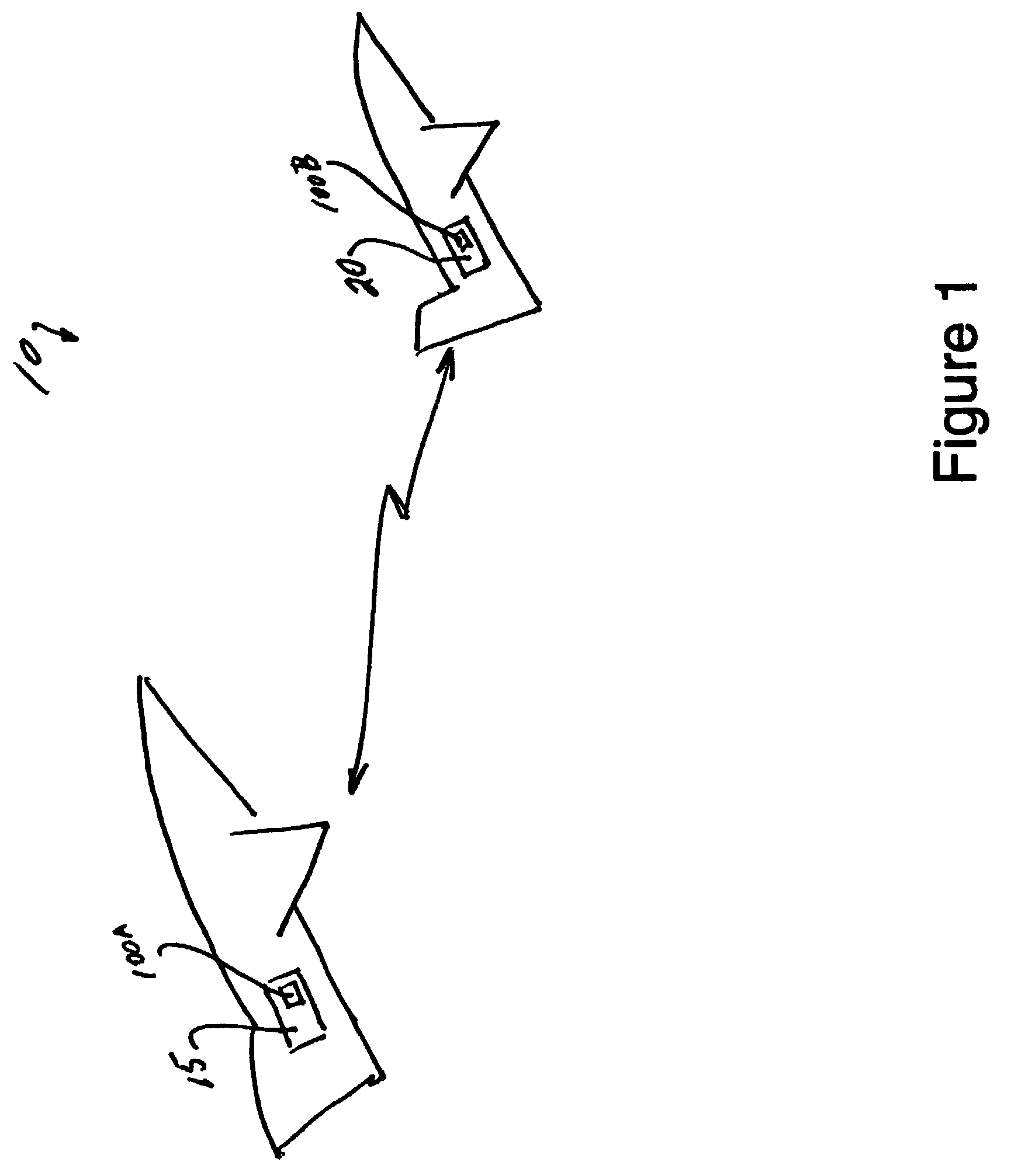
[0022]FIG. 1 shows a diagram of 2 aircraft that may utilize a digital communication system 10 including a first airborne platform, referred to hereinafter as a central platform 15, and a second airborne platform, referred to hereinafter as a terminal platform 20. Central platform 15 and terminal platform 20 may use TDMA technology to communicate with each other. While the present invention may be discussed in the context of airborne platforms, it should be understood that the present invention may be utilized in any terrestrial or non terrestrial applications, including space, air, water, or land based applications, or combination of applications.

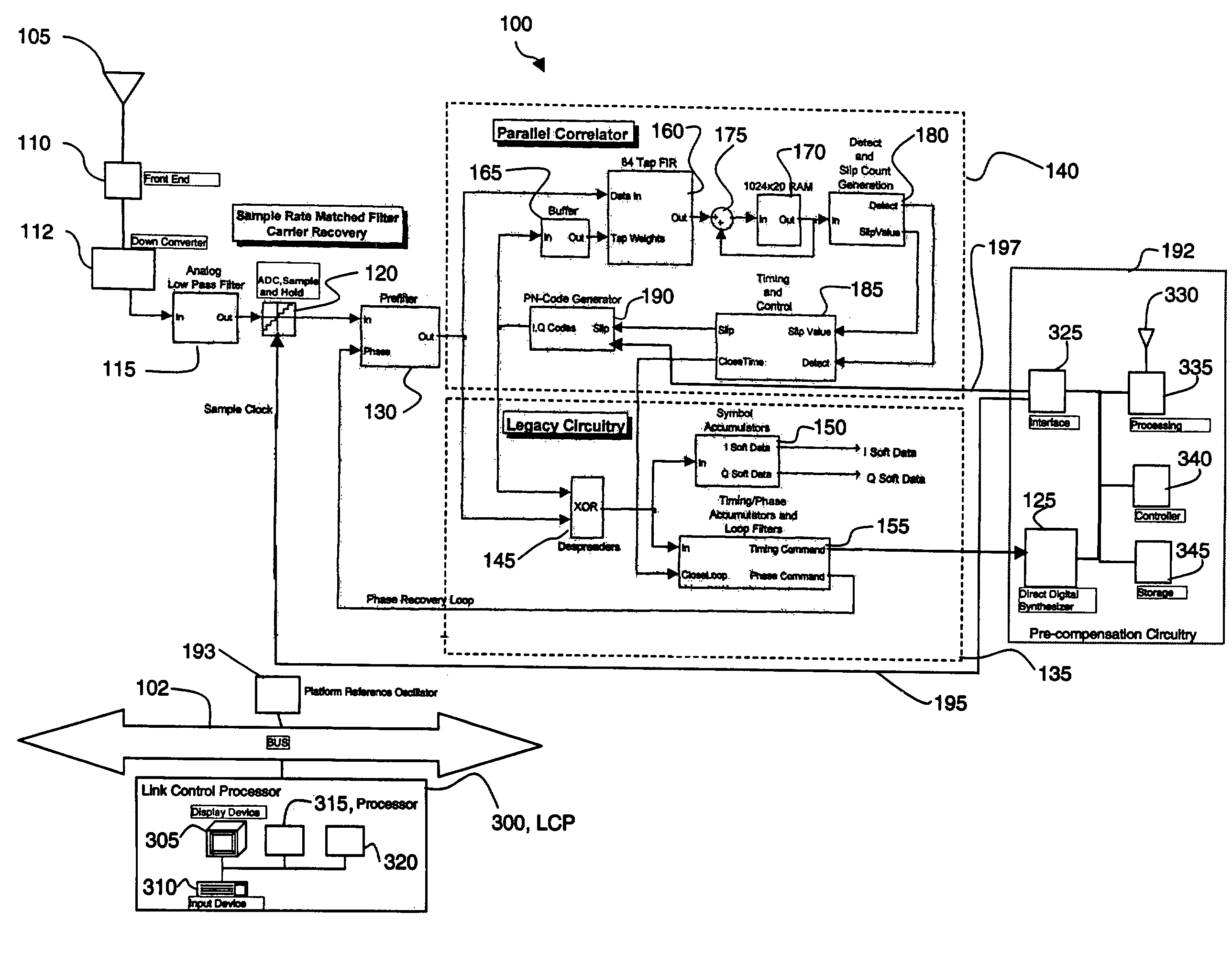
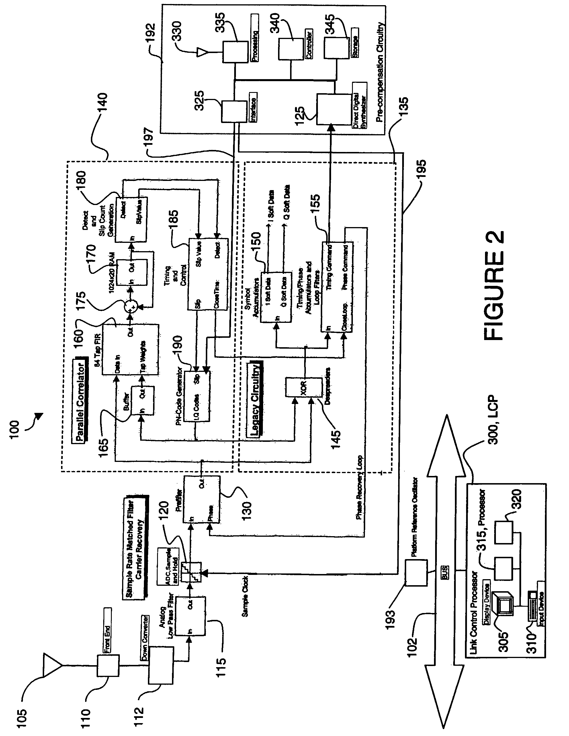
[0023]Referring to FIG. 2, a block diagram of a digital demodulator system 100 incorporating features of the present invention is illustrated. Although the present invention will be described with reference to the embodiment shown in the drawings, it should be understood that the present invention can be embodied in many alternate forms....


PUM


Abstract

A digital communication system includes a generator for generating a plurality of pulse trains, each having a different timing, and pre-compensation circuitry for synchronizing the plurality of pulse trains to a timing signal. The system also includes comparison circuitry for simultaneously comparing a received burst code signal to each of the plurality of pulse trains, where the burst code signal is synchronized to the timing signal, and a detector for detecting which of the pulse trains is a closest temporal match to the burst code signal. The pre-compensation circuitry operates to reduce acquisition time and keep PN code uncertainties within the range of the comparison circuitry.

Description

CROSS REFERENCES TO RELATED APPLICATIONS[0001]The present application is related to U.S. Pat. Nos. 6,201,843, 5,134,631, 5,128,958, 5,105,437, 5,062,071, 5,099,494, 5,060,180, 5,084,913, 5,101,370, 4,841,552, 4,808,939, and 5,022,048.BACKGROUND OF THE INVENTION[0002]1. Field of the Invention[0003]The present invention relates to signal correlation and, more particularly, to parallel correlation of burst code signals in a digital communications system using a timing signal and range rate pre-compensation circuitry to reduce acquisition time.[0004]2. Brief Description of Related Developments[0005]In digital communications systems, information from different sources may be transmitted in different time slots. At the beginning of each time slot, transmitted information may include a preamble having synchronization (sync) bits followed by a number of data bits. If a high data transmission rate is being used, it is important to rapidly detect and synchronize to the sync bits in order to d...

Claims


Application Information

Patent Timeline
Patent Type & Authority Patents(United States)
IPC IPC(8): H04L7/00H04L7/04H04B7/15H04B7/185G01S1/00
CPCH04B1/7075H04B2201/70715
Inventor KELLER, MERLE L.KINGSTON, SAMUEL CHARLESBARHAM, STEVENLUNDQUIST, ALAN EARLBAGLEY, ZACHARY C.WILLES, WARREN PAULMAZAHREH, RAIED N.MCENTIRE, STEVEN J.
Owner L3 TECH INC
Why Eureka
Try Eureka