
System and method for detecting heliostat failures using artificial light sources

a technology of artificial light source and heliostat, which is applied in the safety of solar heat collectors, instruments, lighting and heating apparatus, etc., can solve the problems of motor malfunction, decrement of the average field availability, and inability to reliably reflect sunlight onto the receiver, etc., to achieve the effect of facilitating rapid replacement and restoration and higher degree of parallel data collection

Active Publication Date: 2016-06-21
SEPCOIII ELECTRIC POWER CONSTR CO LTD
View PDF15 Cites 2 Cited by
  • Summary
  • Abstract
  • Description
  • Claims
  • Application Information

AI Technical Summary

Benefits of technology

This method significantly reduces the mean time to repair heliostats and maintains power production by enabling quick identification and maintenance of faulty units, improving overall heliostat availability and reducing the time required for calibration tests.

Problems solved by technology

If a heliostat malfunctions or is otherwise out of service, it is unable to reliably reflect sunlight onto the receiver and so decrements the average availability of the field.
These may include complications such as motor malfunctions, short circuits, blown fuses, or improper wiring.
It is far harder to detect heliostats which remain capable of actuation and communication, but are no longer capable of delivering flux to the receiver accurately and on demand.
This scenario may occur if a heliostat has a broken mirror, has experienced a mechanical failure such as a loose bearing or bolt, or has been disturbed by either personnel, field equipment, or environmental forces (such as wind).
The shortcomings of this approach are that it may take a very long amount of time to test every heliostat in an entire field, and any heliostats that are undergoing routine pointing to a target rather than the receiver are unavailable for power production.
This method may prove to be ineffective due to the dependency of flux delivery on a variety of factors including, but not limited to, cloud cover, natural variations in direct normal solar insolation (DNI), and reflector cleanliness.
Passive monitoring of plant characteristics like flux delivery and receiver temperature do not assist in identifying which heliostats amongst possibly thousands are to blame, requiring additional time and costs for subsequent focused investigations.

Method used


Image

  • System and method for detecting heliostat failures using artificial light sources
  • System and method for detecting heliostat failures using artificial light sources
  • System and method for detecting heliostat failures using artificial light sources

Examples


first embodiment

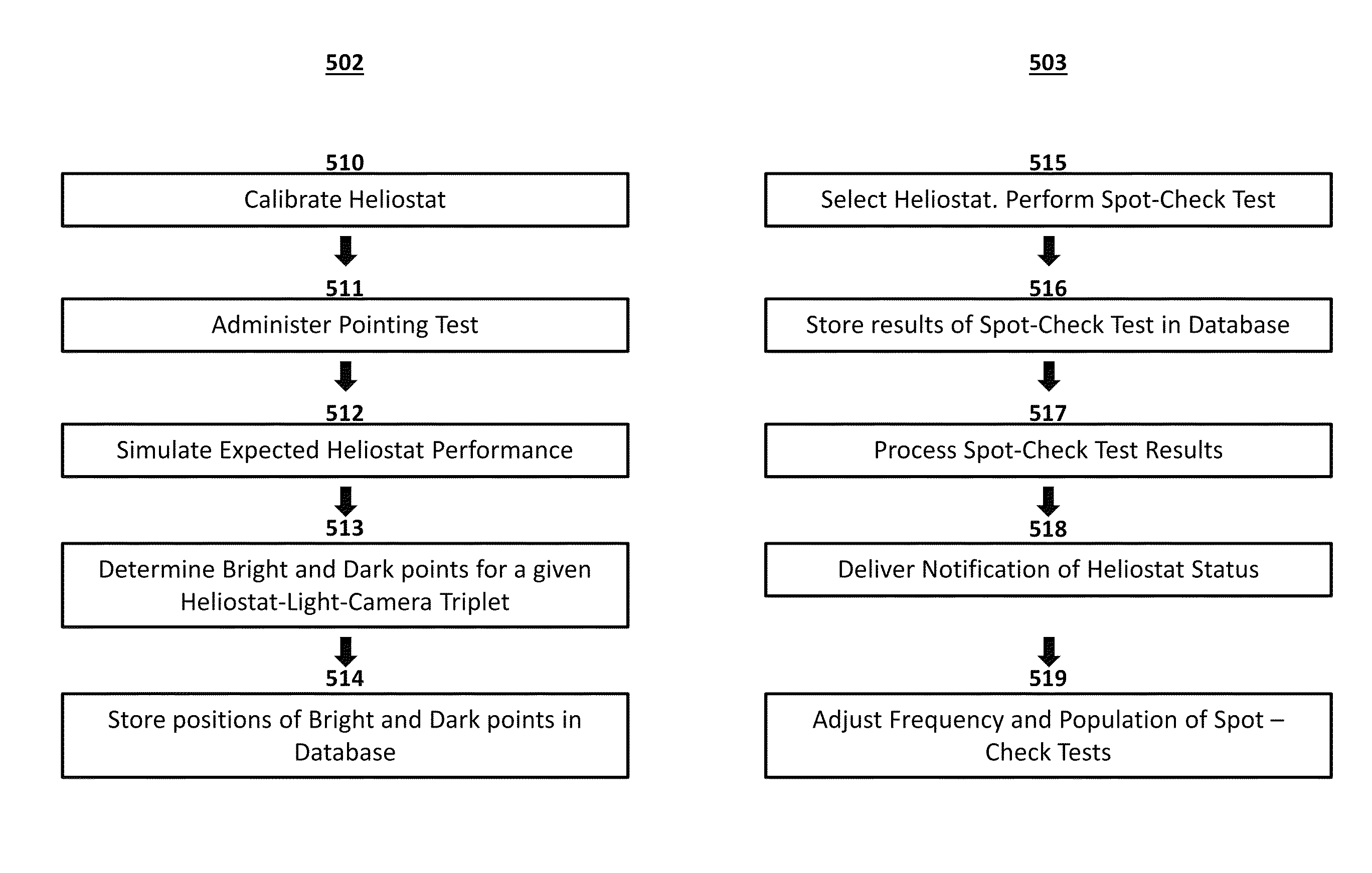
[0042]FIG. 5 displays a flowchart 501 detailing the steps of a method of detecting heliostat failures according to the present invention. The method comprises two phases: a commissioning phase 502 and a monitoring phase 503. The commissioning phase 502 comprises the following steps:[0043]a) Calibrate the heliostat and define characterization function parameters (510). A heliostat may be calibrated by any process that estimates the parameters necessary for it to continuously reflect sunlight onto a receiver tower under open-loop control. For example, a heliostat may be actuated so as to produce a reflection of a given light source in such a way that it is detectable by a given camera, and the control system may record information related to the heliostat's angular orientation at which one or more such reflections were produced, such as the step positions of the motors, as well as the time at which such a reflection occurred, the sun's current position, and other environmental conditi...

second embodiment

[0068]In a second embodiment, scheduling of heliostat spot-check tests may be performed adaptively. Adaptive scheduling involves running spot-check tests of varying duration. In this embodiment, heliostats may be selected for failure mode detection testing based on an objective function, subject to the constraint that no two simultaneous spot checks may interfere with one another. The objective function may prioritize, for example, heliostats which have a higher assumed likelihood of failure. Spot-check tests are performed on subsequent sets of heliostats until they are completed, regardless of duration. The data collection rate may be dynamically controlled based on other plant activities or constraints. For example, if heliostat motion results in higher-than-desired power consumption due to motor actuation, the number of heliostats that are scheduled for spot-check tests during a given time may be throttled to a lower amount. As with deterministic scheduling, heliostats may be que...


PUM

PropertyMeasurementUnit
frequencyaaaaaaaaaa
reflectionaaaaaaaaaa
pressureaaaaaaaaaa

Abstract

A system and method for detecting heliostat failures in a concentrating solar plant, the system comprising a plurality of stationary lights and cameras mounted to towers that surround, or are situated within, a field of heliostats. Heliostats may be commanded via a control system to move to a position wherein light may be expected to be reflected from a given stationary light to a given camera, whereupon a first set of images of the heliostat are taken. Heliostats may then be commanded via the control system to move to a position wherein light may no longer be expected to be reflected from said stationary light to said camera, whereupon a second set of images of the heliostat are taken. An image processor may search the first and second set of images to determine if reflected light is present. If reflected light from said stationary light is not found in the images, the heliostat may be determined to have experienced a failure mode. Failed heliostats may then be flagged for inspection, repair, or replacement.

Description

CROSS-REFERENCES TO RELATED APPLICATIONS[0001]The present application claims priority to and the benefit of U.S. Provisional Patent Application No. 62 / 048,783, filed on Sep. 10, 2014, the entire disclosure of which is incorporated herein by reference.BACKGROUND OF THE INVENTION[0002]This disclosure relates generally to a system and method for detecting failed heliostats in a concentrating solar field. In particular, the invention relates to an improved system and method for assessing heliostat operability by reflecting artificial light from heliostats onto camera imagers.[0003]In Concentrating Solar Power (CSP) plants an array of heliostats reflect sunlight toward a receiver mounted atop a tower and containing a working fluid. The working fluid may be, for example, water or molten salts. One type of receiver transfers incident radiant energy to the working fluid to produce high-pressure, high-temperature steam, which may later be fed to a turbine for electrical power generation. Hel...

Claims


Application Information

Patent Timeline
Patent Type & Authority Patents(United States)
IPC IPC(8): G01N21/88G01N21/55
CPCG01N21/8851G01N21/55G01N2021/8887G01N2201/062Y02E10/47F24S50/20F24S40/90
Inventor ZAVODNY, MAXIMILIAN
Owner SEPCOIII ELECTRIC POWER CONSTR CO LTD
Learn More