Load bearing laminates

a load-bearing laminate and load-bearing technology, which is applied in the direction of layered products, special door/window arrangements, chemistry apparatus and processes, etc., can solve the problems of unsatisfactory jointing techniques which place a load on the laminate, unfavorable application, and difficult to implement. , to achieve the effect of significantly reducing or eliminating the problem of delamination

Active Publication Date: 2010-11-02
PILKINGTON GROUP LTD
View PDF17 Cites 1 Cited by
  • Summary
  • Abstract
  • Description
  • Claims
  • Application Information

AI Technical Summary

Benefits of technology

[0004]We have discovered that this problem of delamination may be significantly reduced or eliminated by inserting a seal between the glass plies which seal surrounds the bore and excludes the bonding layer from the area surrounding the bore. A load bearing insert may be positioned in the void defined by the plies and the seal.

Problems solved by technology

One difficulty which arises in forming such assemblies is that jointing techniques which place a load on the laminate are not ideal.
When the clamp is tightened the bonding layer creeps under the load which detracts from the appearance of the laminate and which may have detrimental consequences.
This solution is difficult to put into practice and is not entirely effective.

Method used


Image

  • Load bearing laminates
  • Load bearing laminates
  • Load bearing laminates

Examples


Embodiment Construction

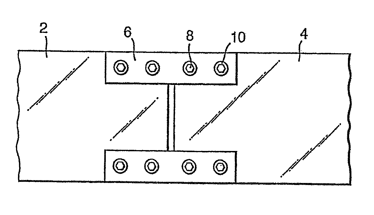
[0025]FIG. 1 shows two separate laminated panels 2 and 4 which are connected by splice plates 6. Bolt assemblies 8 include washers 10 and pass through plate 6 and one of the panels 2 or 4. The Figure shows eight bolt heads 8 and washers 10 but for clarity only one is identified by these reference numerals.

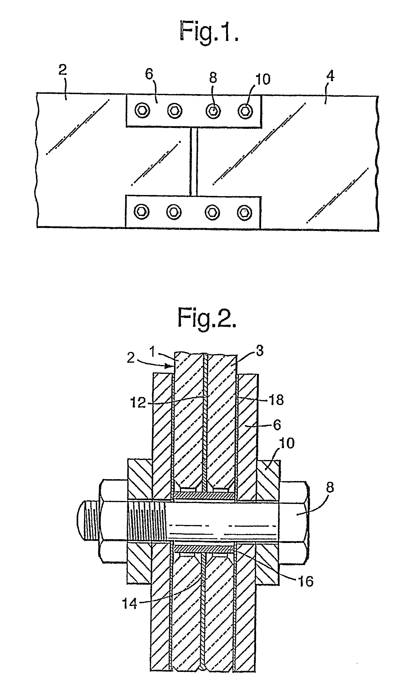
[0026]FIG. 2 shows a panel 2 comprising plies1 and 3. Plies 1 and 3 are joined by interlayer 12. Insert 14 lies between plies 1 and 3 and surrounds the bore through which bolt 8 passes. Bush 16 sits in the bore. Plate 6 acts against fibre gasket 18.

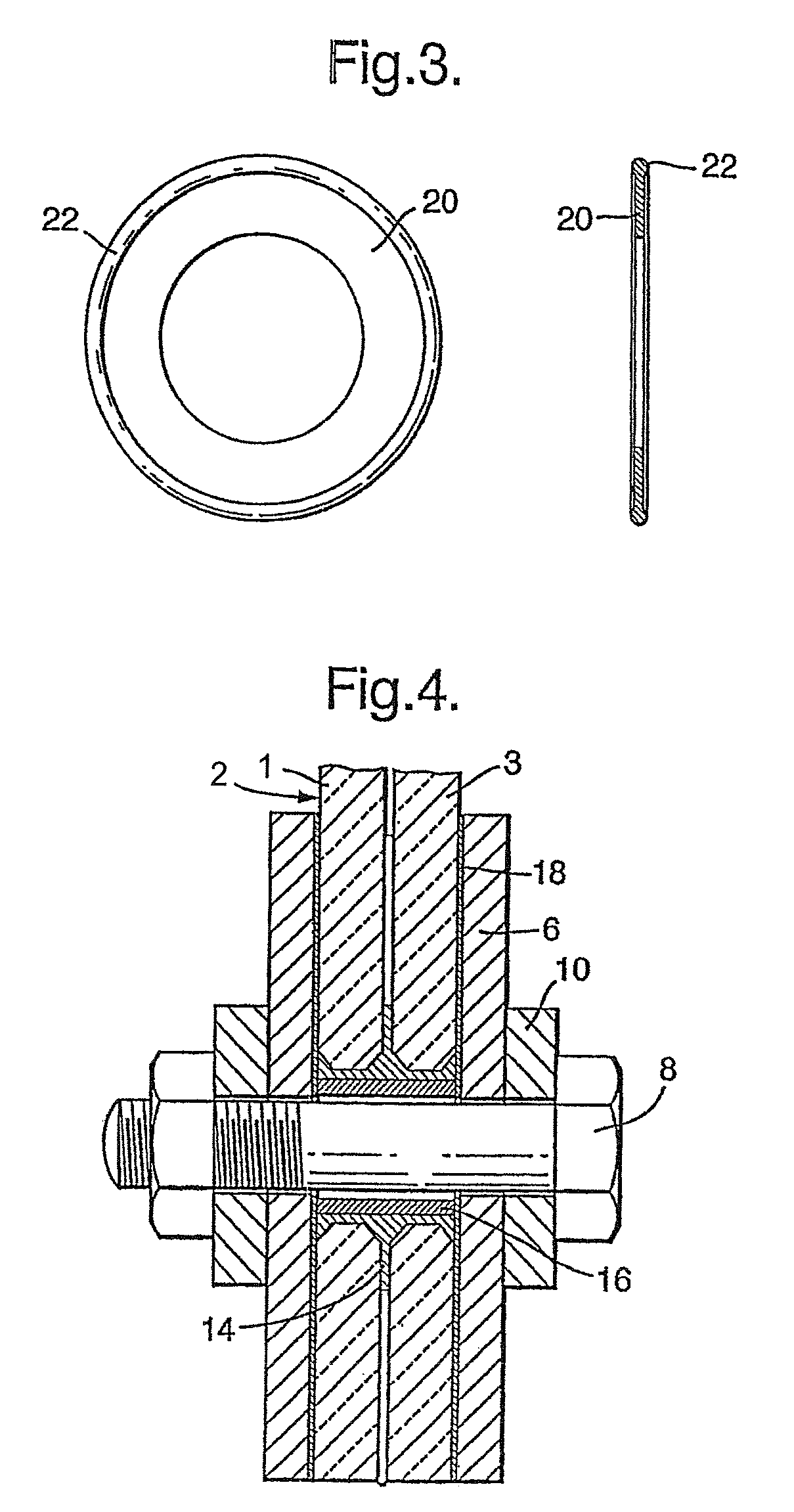
[0027]FIG. 3 shows Insert 14. Insert 14 comprises annular disc 20 having a rubber ring 22 extending around its outer circumference.

[0028]FIG. 4 shows panel 2 comprising plies 1 and 3. Insert 14 occupies the space between bush 16 and plies 1 and 3. Other identifying numerals show in FIG. 4 identify the same feature as is described above in relation to FIG. 2 and are not separately described here.

[0029]The assembly of FIG. 2 is constructed...


PUM

PropertyMeasurementUnit
thicknessaaaaaaaaaa
thicknessaaaaaaaaaa
thicknessaaaaaaaaaa

Abstract

Laminates comprising at least two glass plys surrounding at least one interlayer having at least one bore extending through the laminate are produced by excluding the interlayer from the area surrounding the bore(s) and positioning a load bearing insert around the bore. The insert may be positioned before or after the laminating process. The invention reduces the tendency for delamination around the area of the bore when the laminate is placed under load.

Description

BACKGROUND OF THE INVENTION[0001]This invention relates to methods for the assembly of laminate panels, to laminates capable of supporting loads and to glass assemblies incorporating such laminates.[0002]Laminated panels, in particular glass laminated panels comprising at least two glass plies joined together by a bonding layer which may be a thermoplastic layer, most commonly polyvinylbutyral (hereinafter for convenience PVB) may be joined together or attached to a supporting structure to form a variety of glass assemblies such as a glass façade. One difficulty which arises in forming such assemblies is that jointing techniques which place a load on the laminate are not ideal. One example is those assemblies which utilise clamping plates joined together by bolts passing through a bore in the laminate. In order to form an assembly comprising such a laminate a force of up to ten tonnes may be applied across the laminate. When the clamp is tightened the bonding layer creeps under the ...

Claims


Application Information

Patent Timeline
Patent Type & Authority Patents(United States)
IPC IPC(8): E06B3/54B32B17/10
CPCB32B17/10036B32B17/10825E06B3/5436B32B17/10743B32B17/10761
Inventor WARD, PETERROWLAND, ERICBRUNT, WILLIAM HENRY
Owner PILKINGTON GROUP LTD
Why Eureka
Try Eureka