Motor or generator and method of producing the same

a technology of motors and generators, applied in the direction of windings, dynamo-electric components, magnetic circuit shapes/forms/construction, etc., can solve the problems of complex configuration of stator cores, limited coils to concentrated windings, and increased labor for winding operations, so as to improve the efficiency of motors or generators, the effect of simple coil forming operation

Inactive Publication Date: 2005-04-21
TOYOTA IND CORP
View PDF6 Cites 2 Cited by
  • Summary
  • Abstract
  • Description
  • Claims
  • Application Information

AI Technical Summary

Benefits of technology

[0018] A motor or a generator of the present invention include an armature wound by a conductor wire. The armature includes an armature iron core provided with a plurality of slots and a coil component formed by repeatedly winding a conductor wire around a forming tool. After the above-mentioned coil component is installed at the armature electric iron core while being cut off at the predetermined part, the ends of the conductor wires forming the coil component are electrically connected at the cut surfaces. Meanwhile, the motor and the generator produced according to this invention can obtain the same effect by implementing the same operation as that of the above-mentioned production method. In the motor and the generator, regarding a coil component, ends of conductor wires forming the coil component may be electrically connected by a connector

Problems solved by technology

In a case where a coil is formed by winding a conductor wire directly around a slot provided at a stator core (especially, in a case where a slot is provided on an inner circumference side of a cylindrical stator core), the labor for a winding operation increases.
According to the method des

Method used


Image

  • Motor or generator and method of producing the same
  • Motor or generator and method of producing the same
  • Motor or generator and method of producing the same

Examples


Embodiment Construction

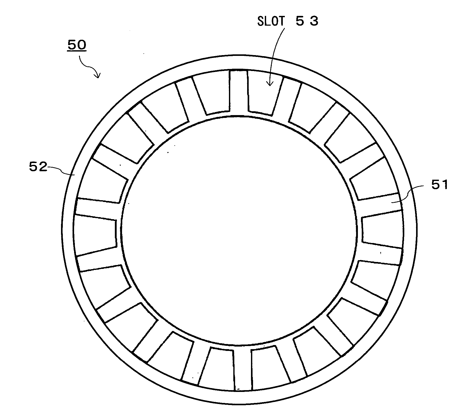
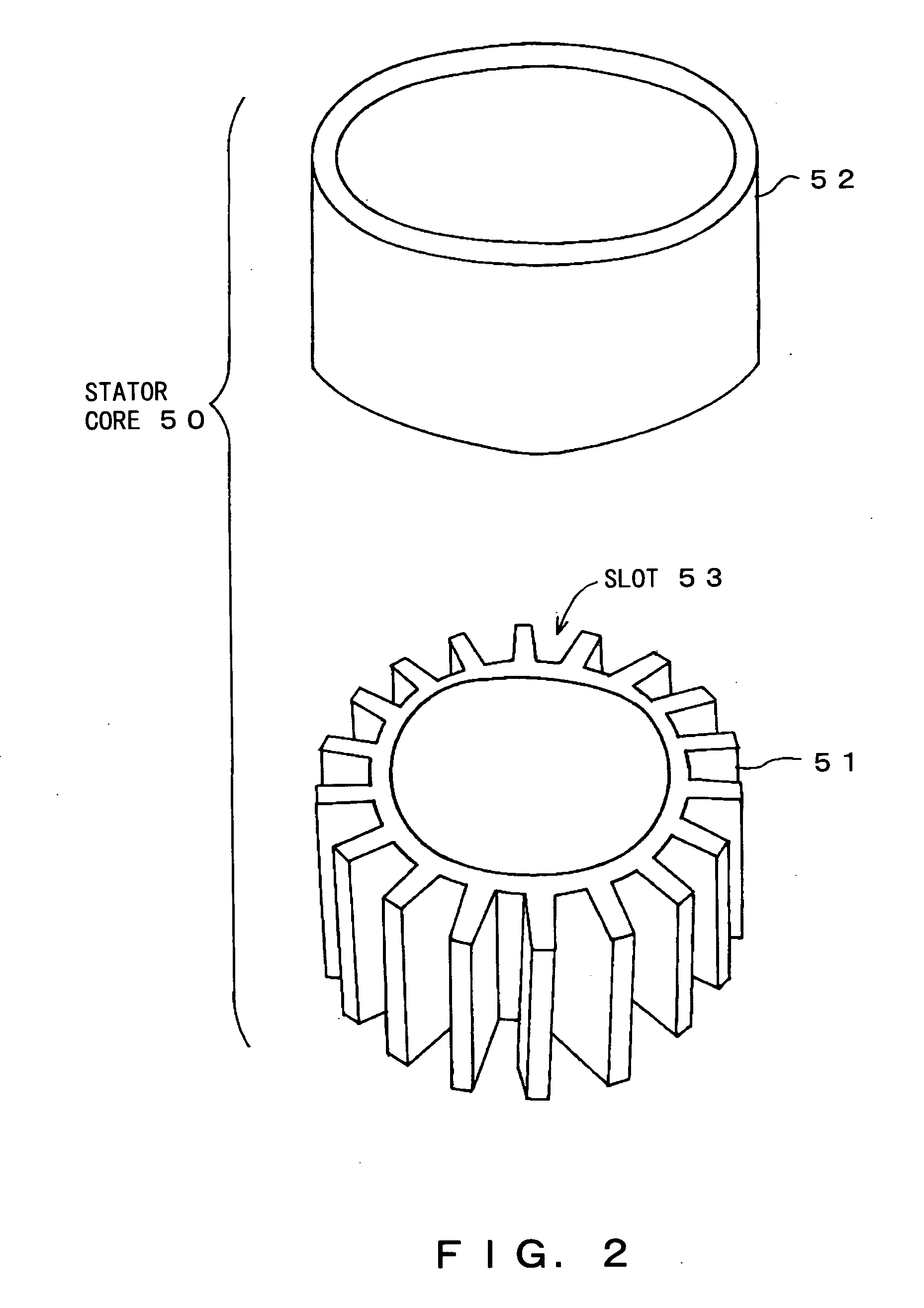
[0033] The following is the explanation of the embodiment of the present invention in reference to the drawings. The explanation is given only for the case where the present invention is applied to a synchronous machine functioning as a rotating electrical unit. Here, the rotating electrical unit of the embodiment includes a motor and a generator. In the following, a case such that the rotating electrical unit is a three-phase rotating electrical unit and the number of poles of each phase is “6” is adopted to be explained.

[0034] The rotating electrical unit of the embodiment includes a stator and a rotor each functioning as an armature similarly to a general rotating electrical unit, but the configuration of the rotor is not characteristic. Therefore, the configuration of the rotor is omitted. Incidentally, steps other than the step of producing a stator may be realized by a general technology or a publicly known technology.

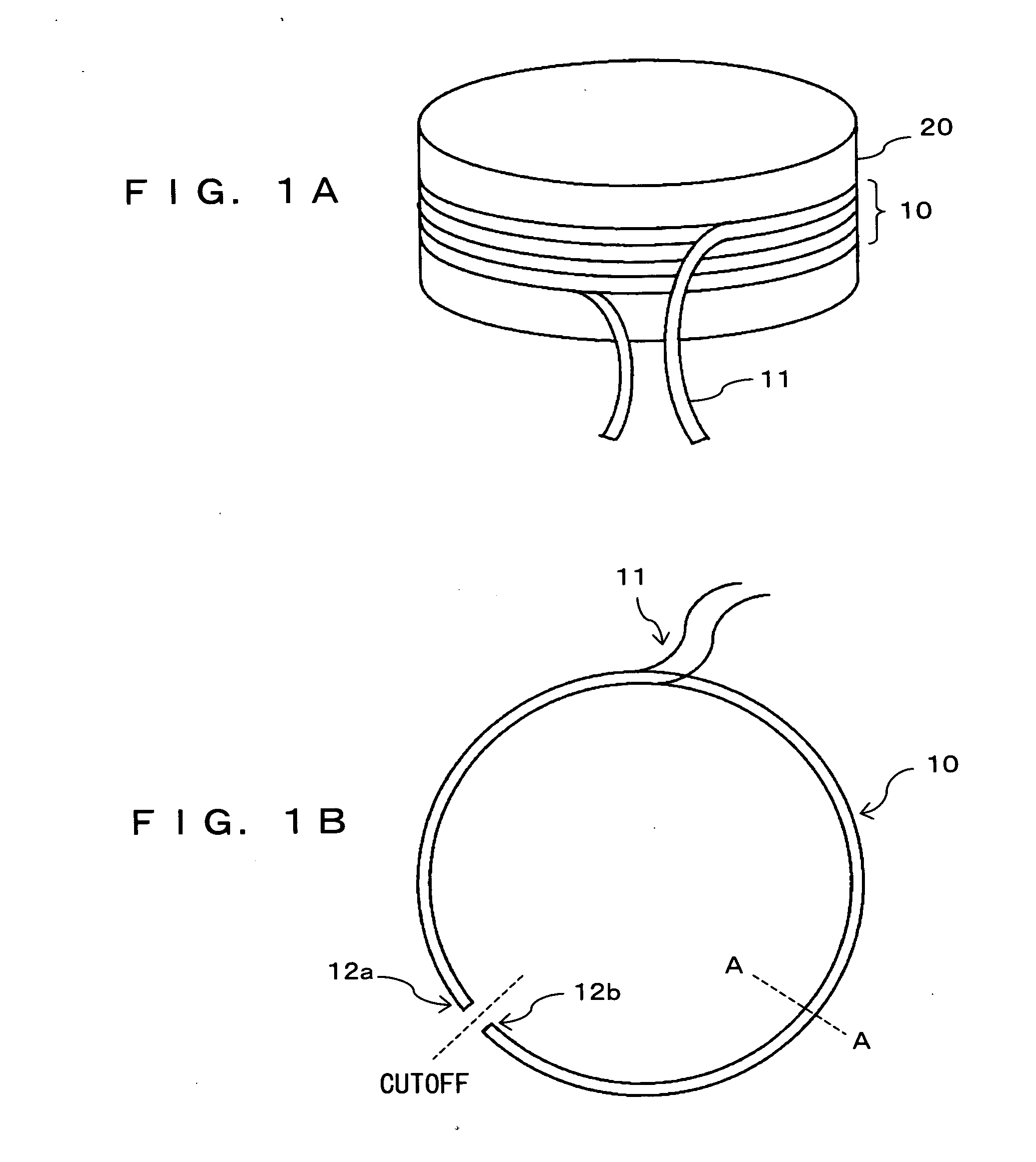
[0035]FIGS. 1A and 1B explain a production method of a co...


PUM


Abstract

A plurality of slots are provided at a stator core. A coil component is produced by winding conductor wires around a forming tool several times. The coil component is cut off at a predetermined part and inserted into a slot so as to cross over the plurality of slots. Then, a coil is formed by connecting the corresponding conductor wires at cut surfaces of the coil component.

Description

BACKGROUND OF THE INVENTION [0001] 1. Field of the Invention [0002] The present invention relates to a motor and a generator of which the armature is wound by a coil and also relates to a method thereof. [0003] 2. Description of the Related Art [0004] A rotating electrical unit has been conventionally and widely used in various fields. Here, the rotating electrical unit includes a motor and a generator. The use of the rotating electrical unit is not limited but here it is used as, for example, a motor for driving the compressor of an air conditioner, a motor for running an electric vehicle (including a hybrid car), a generator mounted on a car, etc. [0005] The rotating electrical unit is generally provided with a coil for generating a magnetic field (in the case of a generator, a coil for generating electromotive force in accordance with the change of a flux). The following method is well known as a method of forming a conventional wire. [0006] For example, in a rotating electrical ...

Claims


Application Information

Patent Timeline
IPC IPC(8): H02K3/04H02K1/00H02K1/14H02K3/00H02K3/28H02K3/32H02K15/00H02K15/04H02K15/06H02K15/085
CPCH02K1/148H02K3/12H02K15/0056H02K15/0075H02K2203/15H02K15/0435H02K15/064H02K15/085H02K15/0081H02K15/0068H02K15/0485
Inventor FUKASAKU, HIROSHIUETSUJI, KIYOSHI
Owner TOYOTA IND CORP
Why Eureka
Try Eureka