
Product management display system with trackless pusher mechanism

a technology of pusher mechanism and product management, which is applied in the field of shelf assembly, can solve the problems of affecting the proper operation of the pusher system, affecting the forward movement of the pusher mechanism, and occupying a large amount of shelving, and achieves the effect of enhancing the forward movemen

Active Publication Date: 2010-11-02
RTC IND
View PDF423 Cites 189 Cited by
  • Summary
  • Abstract
  • Description
  • Claims
  • Application Information

AI Technical Summary

Benefits of technology

The trackless pusher mechanism ensures continuous and efficient product movement towards the front of shelves, preventing tipping and binding issues, maintaining product visibility and accessibility, and accommodating various product shapes and sizes.

Problems solved by technology

It is known that retail and wholesale stores, such as convenience stores, drug stores, grocery stores, discount stores, and the like, require a large amount of shelving both to store product and to display the product to consumers.
However, over time, these surfaces can become obstructed with debris or sticky substances that inhibit the product from properly sliding, sometimes causing several products to tip over thus blocking additional product from moving to the front of the shelf.
Occasionally, as the system is used, and over time, the track becomes obstructed with dirt or sticky materials that hinder the proper operation of the pusher system in the track.
In addition, depending on the size, shape and weight of the product to be merchandised, the known pusher paddles may occasionally tip or bend backwards, thereby causing a binding of the pusher mechanism in the track.
In those situations, the pusher mechanism may not properly push product toward the front of the shelf.

Method used


Image

  • Product management display system with trackless pusher mechanism
  • Product management display system with trackless pusher mechanism
  • Product management display system with trackless pusher mechanism

Examples


Embodiment Construction

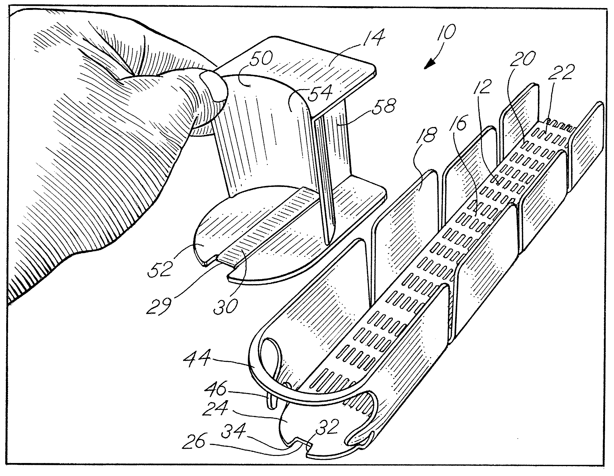
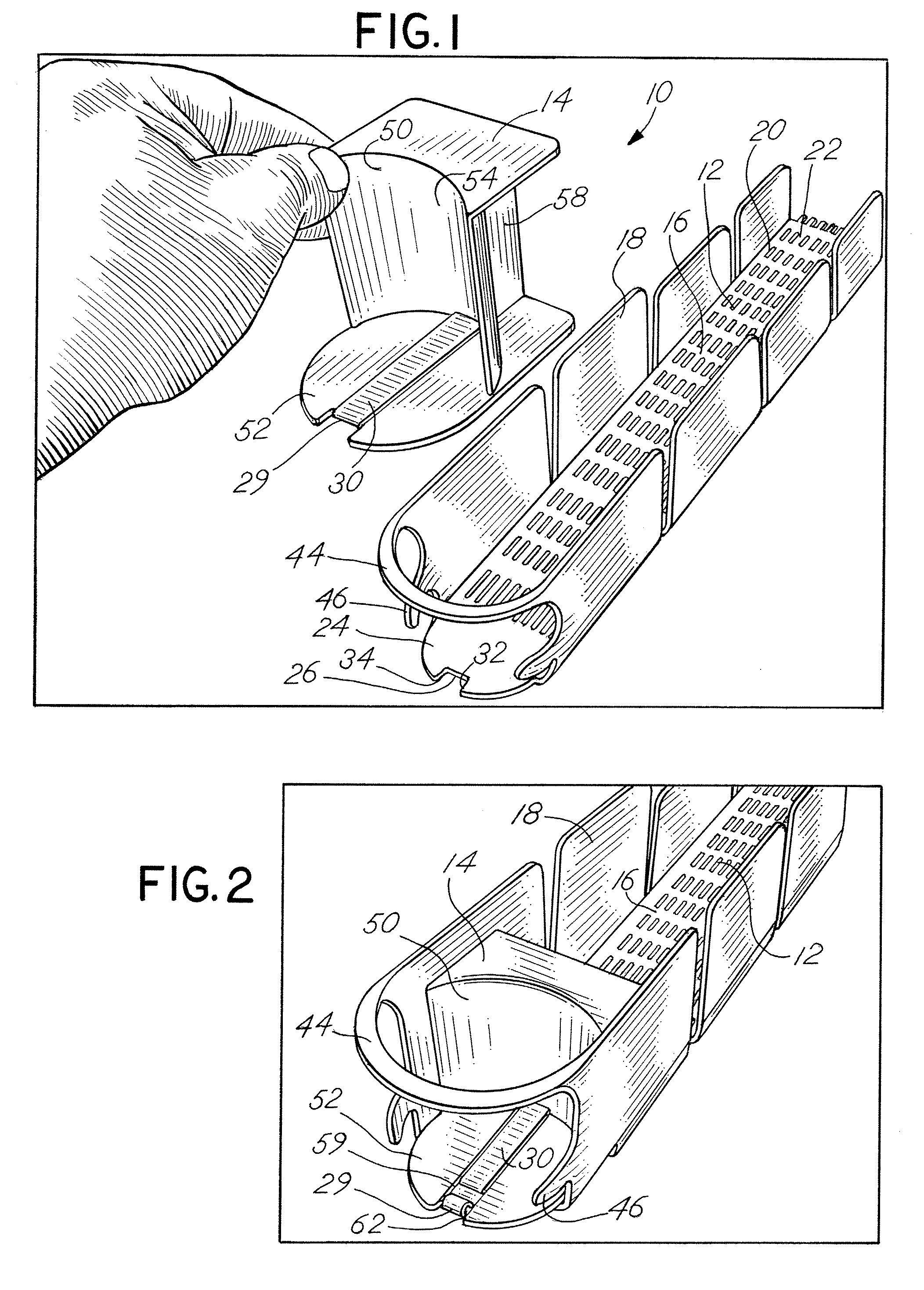
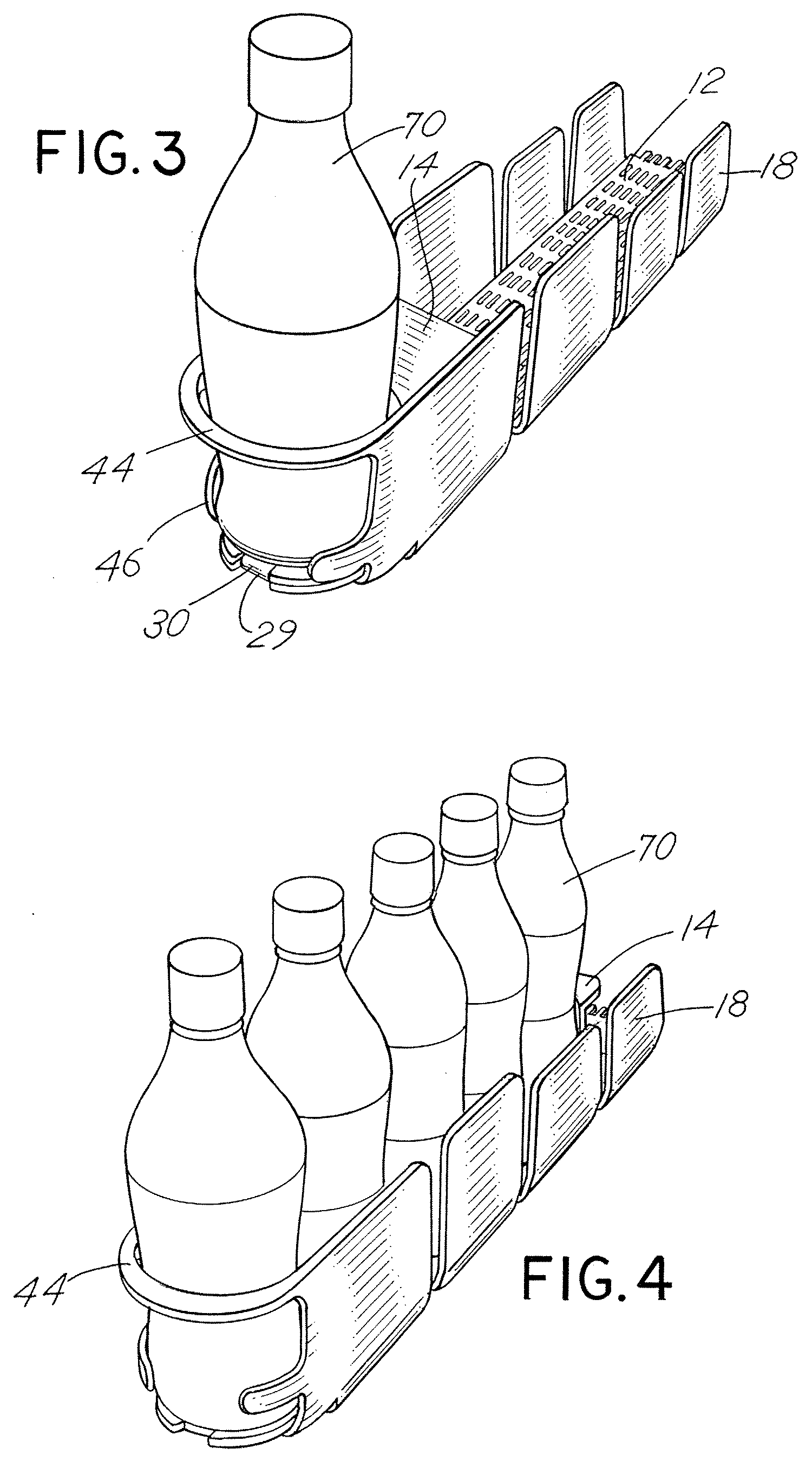
[0034]The invention may be embodied in various forms. Referring to the Figures wherein like numerals indicate like elements, there is depicted in FIG. 1 an isometric exploded view of an exemplary embodiment of the present invention. Exemplary merchandise system 10 includes a product dispensing tray 12 in which is mounted an exemplary trackless pusher mechanism 14. As described in more detail below, the pusher mechanism 14 will fit in the tray 12 and will slide along the surface of the tray without the use of tracks, rails, or guides typically used to hold a conventional pusher mechanism to the tray or floor of the tray. The pusher mechanism defines a pusher paddle and a pusher floor that extends forward of the pusher paddle. A coiled spring may extend across the pusher floor and operatively connect to the tray at a forward position on the tray. In one aspect of the invention, product to be merchandised may be placed in the tray in front of the pusher paddle and may sit on the pusher...


PUM


Abstract

A product management display system for merchandising product on a shelf includes using a trackless pusher mechanism that travels along a surface on which product is placed. The pusher mechanism of the invention also includes a pusher paddle and a floor that extends forward of the pusher paddle. A flat coiled spring or other biasing element may be operatively connected behind the pusher paddle and extend across the floor of the pusher mechanism and to the front of the shelf. In use, the product to be merchandised may be placed on the coiled spring and on the floor of the pusher mechanism. With this configuration, the pusher paddle is prevented from tipping or bending backwards during operation. The invention may be used with the merchandising of product on horizontal or non-inclined shelves or surfaces, as well as with gravity-fed systems, or systems that use gravity as a mechanism to urge product toward the front of the shelf.

Description

CROSS REFERENCE TO RELATED APPLICATION[0001]This Non-Provisional Application claims benefit to U.S. Provisional Application Ser. Nos. 60 / 716,362 filed Sep. 12, 2005 and 60 / 734,692 filed Nov. 8, 2005, both of which are incorporated herein by reference.FIELD OF THE INVENTION[0002]The present invention relates generally to a shelf assembly for use in merchandising product and more particularly to a shelf assembly having improved mechanisms for displaying and pushing product on the shelves.BACKGROUND OF THE INVENTION[0003]It is known that retail and wholesale stores, such as convenience stores, drug stores, grocery stores, discount stores, and the like, require a large amount of shelving both to store product and to display the product to consumers. In displaying product, it is desirable for the product on the shelves to be situated toward the front of the shelf so that the product is visible and accessible to consumers. In the case of coolers or refrigerators that are used to store and...

Claims


Application Information

Patent Timeline
Patent Type & Authority Patents(United States)
IPC IPC(8): A47F7/00
CPCA47F1/126A47F1/04A47F1/125
Inventor HARDY, STEPHEN N.
Owner RTC IND
Learn More