Air humidification system for large enclosed spaces and humidification module usable in such system

a technology for humidification systems and enclosed spaces, which is applied in the direction of free-cooling systems, machines/engines, and combustion gas purification/modification. it can solve the problems of dripping, inability to install pipes, and inability to absorb moistur

Inactive Publication Date: 2010-11-02
CAREL SPA
View PDF13 Cites 6 Cited by
  • Summary
  • Abstract
  • Description
  • Claims
  • Application Information

AI Technical Summary

Benefits of technology

[0014]The aim of the present invention is to provide a humidification system which allows to solve the drawbacks observed in known types.
[0015]Within this aim, an object of the present invention is to provide a humidification module which allows to avoid spreading water on the ground both during operation and when operation is interrupted.
[0016]Another object of the present invention is to provide a humidification module which is structurally simple and can be assembled easily to provide humidification systems.

Problems solved by technology

In some enclosed spaces, due to the limited height of the ceiling, it might not be possible to install the pipes at the optimum height, with evident problems regarding poor air humidification and the inevitable presence of water on the ground, at least in the presence of ranges of the environmental parameters.
However, these modules, as well as systems of the traditional type in which the nozzles are arranged along simple pipes which are raised from the ground and are not associated with ventilation means, have the problem of dripping when the humidification system is stopped.
When the pumps that supply the water are stopped, the pressure in the pipes in fact does not drop instantly and therefore water at a pressure which is not sufficient to create a good aerosol tends to flow out of the nozzles (even if they are provided with valves which open at a minimum preset pressure level of the ejected stream, for example by means of a spherical flow control element associated with a suitably calibrated spring), introducing into the enclosed space water particles which are too heavy and cannot be absorbed even in the presence of an air stream which extends their path.

Method used


Image

  • Air humidification system for large enclosed spaces and humidification module usable in such system
  • Air humidification system for large enclosed spaces and humidification module usable in such system
  • Air humidification system for large enclosed spaces and humidification module usable in such system

Examples


Embodiment Construction

[0022]It is noted that anything found to be already known during the patenting process is understood not to be claimed and to be the subject of a disclaimer.

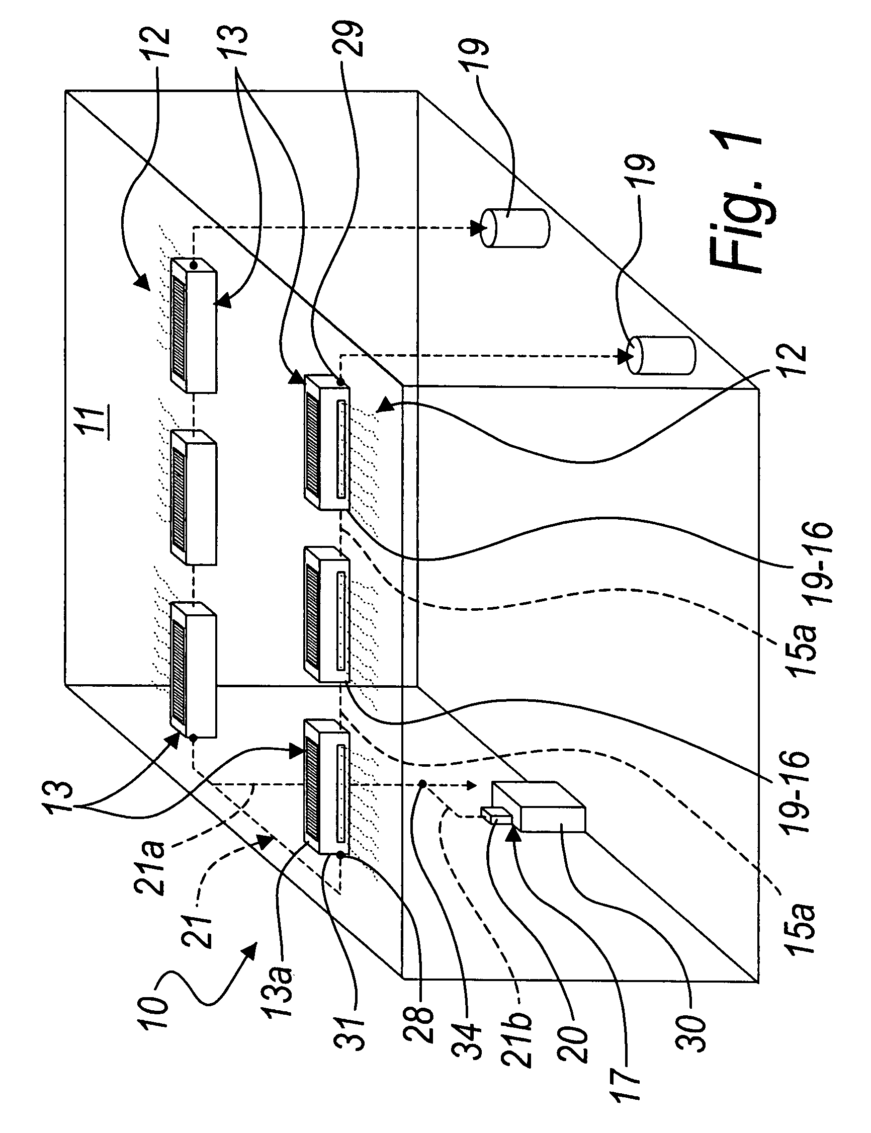
[0023]With reference to the figures, a humidification system according to the invention is generally designated by the reference numeral 10.

[0024]FIG. 1 illustrates the humidification system 10 installed within a large room 11.

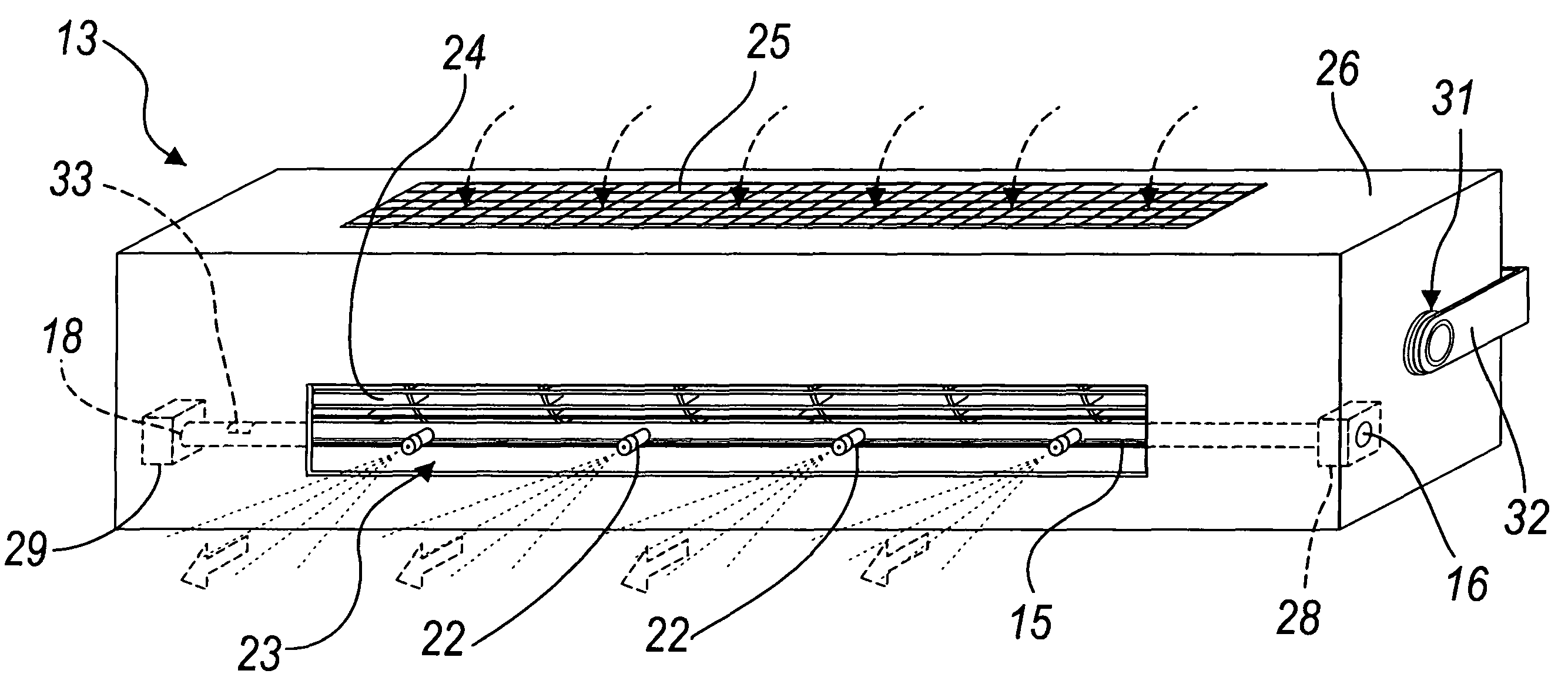
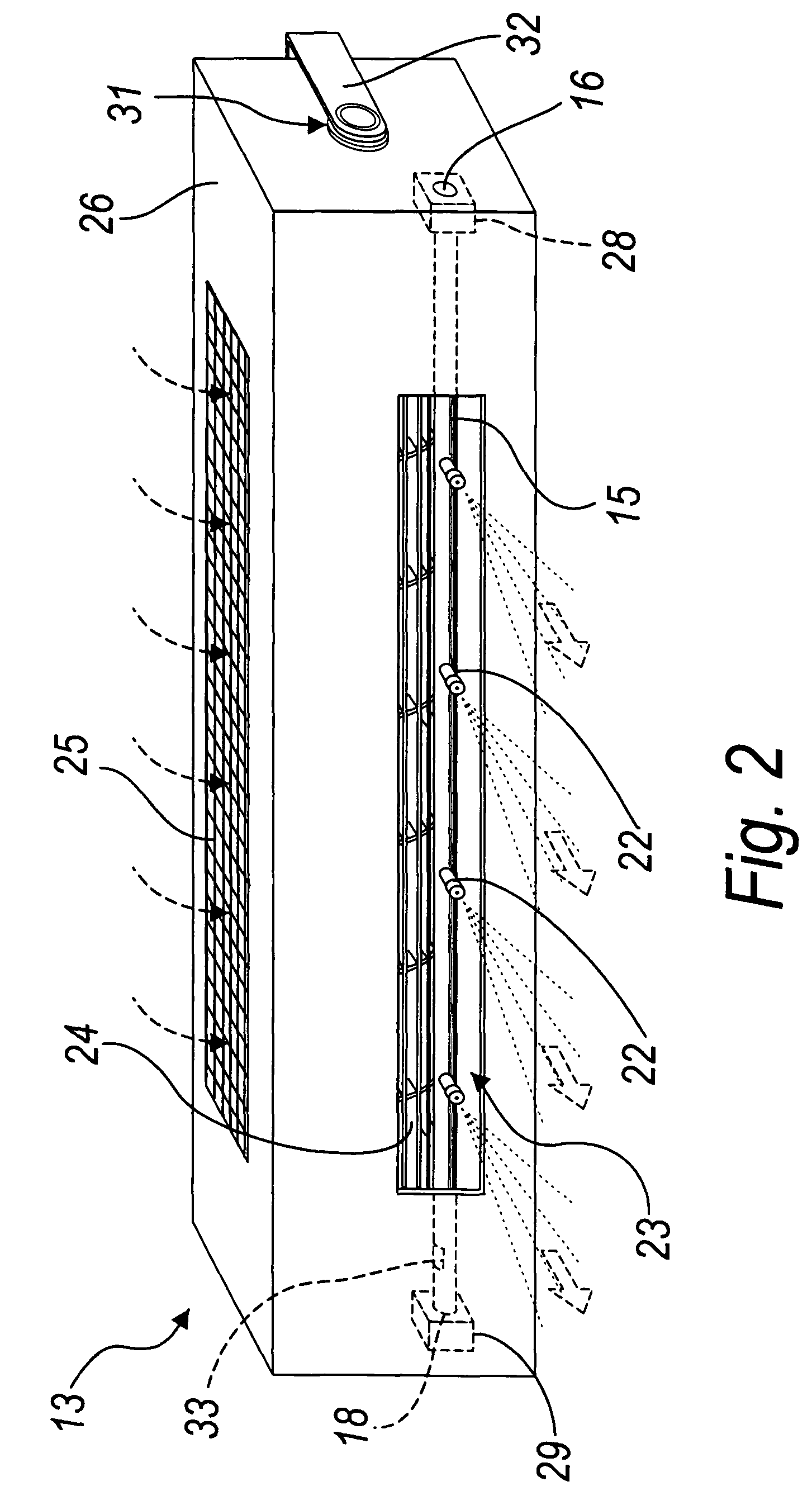
[0025]The system 10 comprises, in this configuration, two parallel humidification lines 12, which are arranged at a certain height from the ground transversely to the room 11; each line 12 comprises, in this configuration, three humidification modules 13 which are connected in series to each other.

[0026]Each humidification module 13 comprises a box-like container 14, which is shaped like a parallelepiped and inside which there is a water passage pipe 15, which is functionally (so as to perform a function, namely water conveyance) connected at its inlet 16 to water pumping means 17 and at its outlet 18 to a...


PUM

PropertyMeasurementUnit
pressureaaaaaaaaaa
pressureaaaaaaaaaa
pressuresaaaaaaaaaa

Abstract

An air humidification system for large enclosed spaces, comprising at least one humidification line constituted by at least one humidification module comprising a box-like container with a water flow pipe inside which is functionally connected at its inlet to a water pump and at its outlet to a water discharge space. The pipe has, along its extension, a plurality of nozzles adapted to provide a water aerosol. The nozzles are open onto a first opening provided in the box-like container and are oriented toward the outside of the first opening. A cross-flow impeller is provided within the box-like container along a rotation axis which is parallel to the pipe and is suitable to aspirate air from a second opening of the box-like container and direct it toward the first opening.

Description

[0001]The present invention relates to an air humidification system for large enclosed spaces and to a humidification module which can be used in such system.BACKGROUND OF THE INVENTION[0002]In many industrial environments, such as for example in the case of the textile, printing, woodworking industries and in other environments, such as preservation cells for fruit and vegetables, as well as in storage areas for paper, wood, et cetera, it is necessary to control ambient humidity.[0003]Enclosed spaces of this type are humidified but also cooled generally by using humidification systems which are constituted by pipes which are suspended from the ground and are connected to means for pumping water.[0004]Nozzles are provided along said pipes and are designed to create a water aerosol which diffuses into the environment, humidifying the air.[0005]To allow the air to absorb the water particles, their path of descent must be long enough.[0006]The length of this path depends on the environ...

Claims


Application Information

Patent Timeline
Patent Type & Authority Patents(United States)
IPC IPC(8): B01F3/04
CPCF24F6/14F24F2006/146Y02B30/545Y02B30/54
Inventor BALDON, STEFANOMARTELLO, MICHELENALINI, LUIGI
Owner CAREL SPA
Why Eureka
Try Eureka