Articulated step system for automotive vehicle

a technology for automotive vehicles and steps, applied in the directions of vehicle components, steps arrangement, transportation and packaging, etc., can solve the problems of limiting the usefulness of the step shown, the height of the pick-up truck is often quite tall, and the lack of mounting ability

Active Publication Date: 2010-11-02
FORD GLOBAL TECH LLC +1
View PDF95 Cites 50 Cited by
  • Summary
  • Abstract
  • Description
  • Claims
  • Application Information

AI Technical Summary

Benefits of technology

[0010]It is an advantage of the present articulated step system that the design and styling of the step may be rendered in a fashion consistent with an existing step bar used in a vehicle such as a pickup truck.
[0011]It is a further advantage of a step system according to the present invention that this system may be installed readily in a vehicle during the vehicle's assembly process, thereby allowing the vehicle, including the step, be delivered to a dealership, and even to the ultimate consumer, without any intervening assembly action.
[0012]It is a further advantage of a system according to the present invention that the articulated step may be employed not only as a smaller step extending wholly under a vehicle body, for example, of a pickup truck, but also as a longer step extending from the front part of a vehicle to a position underneath the pickup box of the vehicle.

Problems solved by technology

Unfortunately, pickup trucks are often quite tall, particularly 4×4 trucks, trucks with large wheel / tire combinations, and trucks that are particularly suited to off-road use.
System of the '303 patent suffers from the fact that its mounting is accomplished by a single bracket bolted to the frame of a vehicle.
Such a mounting may be lacking in terms of its ability to handle the moment created by the weight of an individual upon the step; this limits the usefulness of the step shown in the '303 patent.
As a result, the load carrying capability and robustness of the step shown in the '125 patent is limited.

Method used


Image

  • Articulated step system for automotive vehicle
  • Articulated step system for automotive vehicle
  • Articulated step system for automotive vehicle

Examples


Embodiment Construction

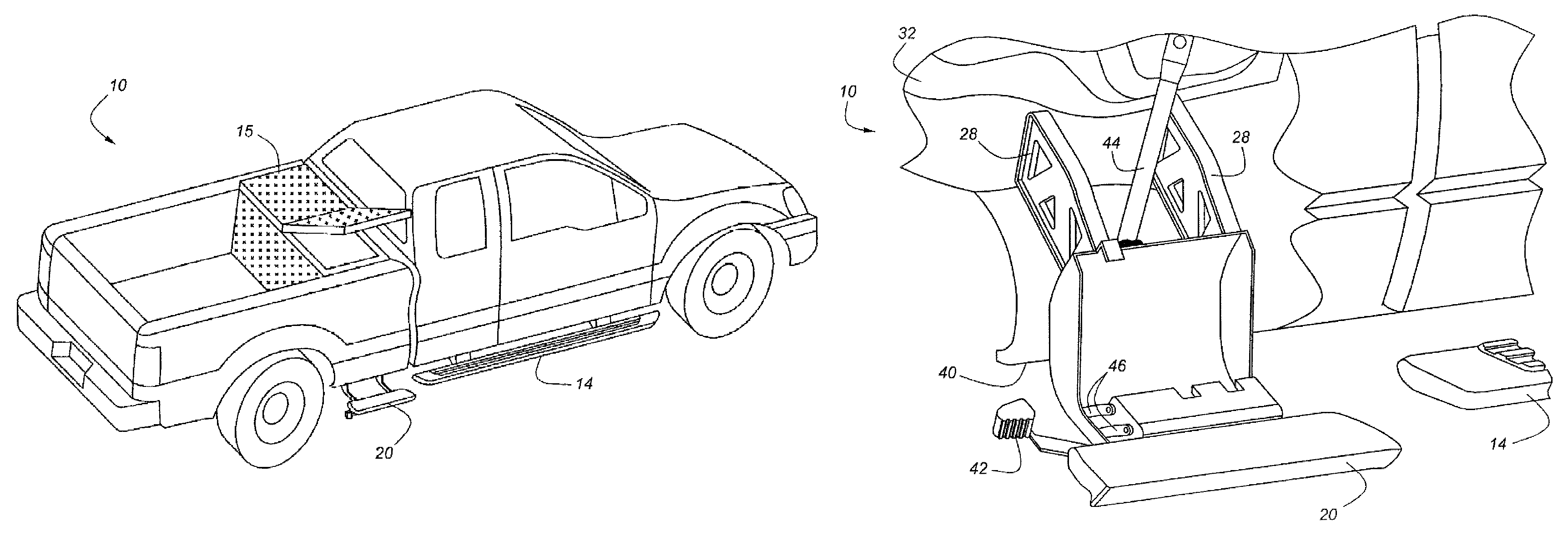
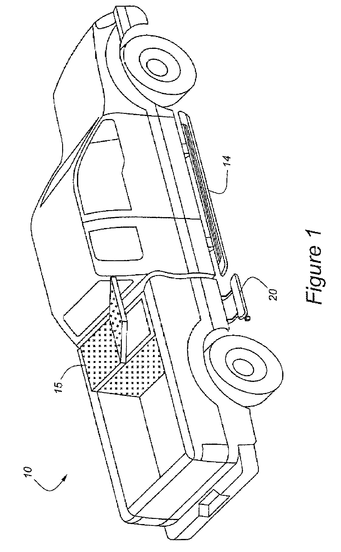
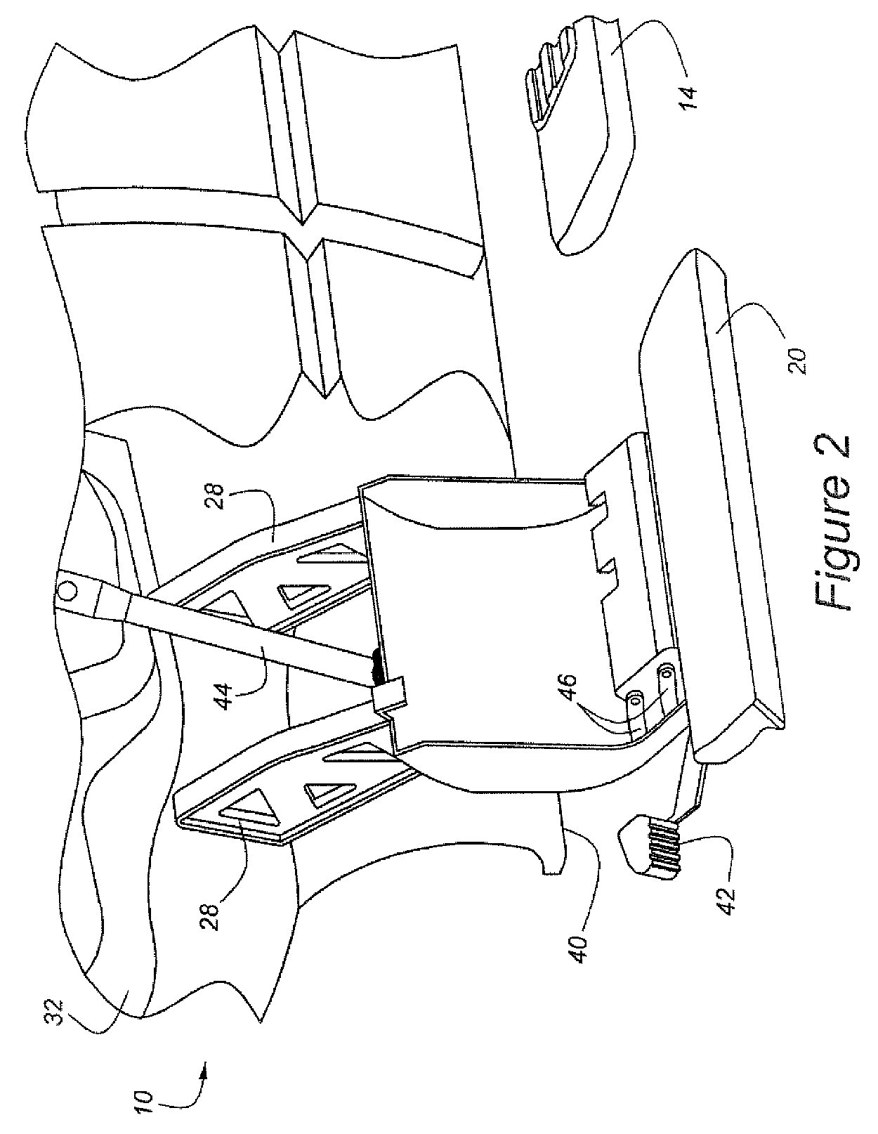
[0028]As shown in FIG. 1, vehicle 10 has a main step, 14, and an articulated step, 20. Step 20 is shown in an unfolded, or deployed, position in FIG. 2. While in the deployed position, step 20 provides ready access to toolbox 15. Step 20 is mounted to step housing 40 by means of four linkage bars, 46, which are pivoted to step housing 40 and to step 20. Two of links 46 are illustrated in FIG. 2. A motorist uses pedal lever 42 to move step 20 from its stored position to its deployed position. Step housing 40 is mounted to vehicle 10 by means of standoff brackets and a tension strut. Standoff brackets 28, extend generally laterally between housing 40 and frame rail 32, which itself extends generally longitudinally along vehicle 10 under the vehicle's body. Tension strut 44 is interposed between housing 40 and a location on the vehicle's body, which is discussed in greater detail below. As used herein, the term “housing” means either a partial enclosure as shown in FIGS. 2 and 3, or a ...


PUM


Abstract

An articulated step system for an automotive vehicle includes a step housing attached to the vehicle frame by means of at least one standoff bracket and a tension strut extending generally downwardly from a first end attached to a vehicle body to a second end attached to the step housing. The articulated step has a stowed position generally underlying the body, and a deployed position extending generally outwardly from the body. Movement of the step may be either translational or rotational with respect to the step housing. In one embodiment, the step extends for the full length of the cab of the vehicle, and partially under a load carrying body at the rear of the vehicle.

Description

CROSS-REFERENCE TO RELATED APPLICATIONS[0001]The present application claims priority to U.S. provisional patent application 60 / 743,204 filed Feb. 1, 2006, and entitled “Articulating Box Access Step”, the disclosure of which is incorporated by reference herein.BACKGROUND OF THE INVENTION[0002]The present invention relates to a deployable step for accessing a portion of a vehicle, such as the interior of the cargo box of a pickup truck.[0003]Utility vehicles, particularly pickup trucks, are used for a wide variety purposes, including the transportation of tradesmen's tools. Such tools are frequently carried in toolboxes mounted at the front of a pickup truck's bed. Unfortunately, pickup trucks are often quite tall, particularly 4×4 trucks, trucks with large wheel / tire combinations, and trucks that are particularly suited to off-road use. Thus, designers have a tended to develop steps allowing access over the sides of pickup trucks to items carried within the bed. Such steps can also b...

Claims


Application Information

Patent Timeline
Patent Type & Authority Patents(United States)
IPC IPC(8): B60R3/02
CPCB60R3/02
Inventor VANBELLE, MICHAELCABALLERO, LOUISSAUERWEIN, SVENBARRETT, DAVID
Owner FORD GLOBAL TECH LLC
Why Eureka
Try Eureka