Bicycle sprocket
a technology for bicycles and sprockets, which is applied in the direction of mechanical equipment, transportation and packaging, hoisting equipment, etc., can solve the problems of reducing attachment forces, deformation of resin fastening parts, and potential loss of attachment forces, so as to prevent looseness or play, maintain rigidity, and facilitate manufacturing. the effect of simplified manufacturing process
- Summary
- Abstract
- Description
- Claims
- Application Information
AI Technical Summary
Benefits of technology
Problems solved by technology
Method used
Image
Examples
second embodiment
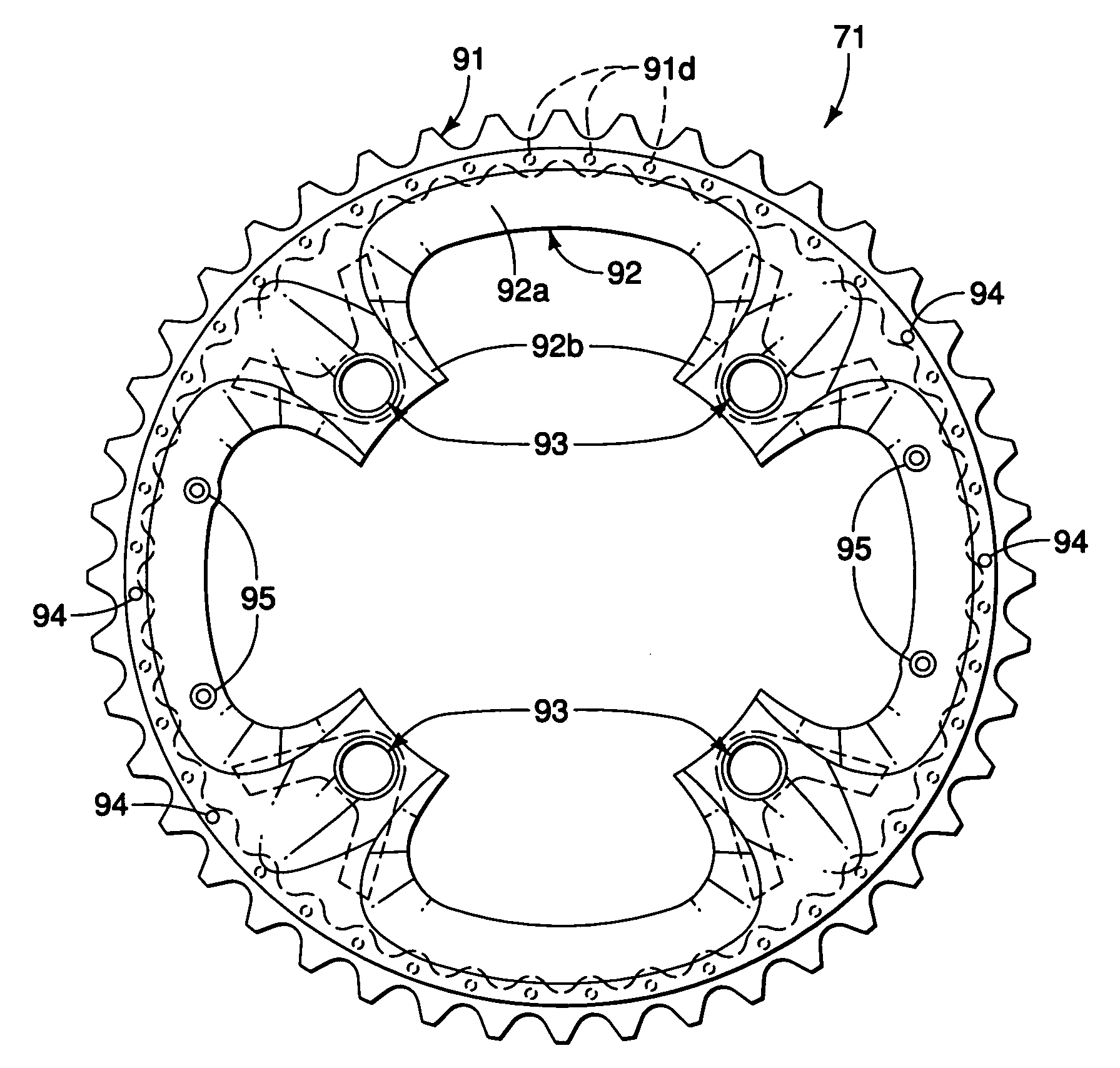
[0104]Referring now to FIGS. 11-14, a sprocket 171 is illustrated in accordance with a second embodiment. The sprocket 171 basically includes a metallic sprocket ring part 191, a synthetic resin fastening part 192 and a plurality of attachment parts 193 with a connecting portion 193a and a radial projecting portion 193b. The sprocket 171 is configured and arranged to replace the sprocket 71 in the crankset 51 of the first embodiment. The sprocket 171 is identical to the sprocket 71, as discussed above, except that the attachment parts 193 have been modified in comparison to the attachment parts 93. In view of the similarity between the first and second embodiment, the descriptions of the parts of the second embodiment that are identical to the parts of the first embodiment may be omitted for the sake of brevity. Thus, unless otherwise specified or illustrated, the descriptions of the parts of the first embodiment applies to the corresponding part of the second embodiment.
[0105]In th...
third embodiment
[0106]Referring now to FIGS. 15-17, a sprocket 271 is illustrated in accordance with a third embodiment. The sprocket 271 basically includes a metallic sprocket ring part 291, a synthetic resin fastening part 292 and a plurality of attachment parts 293 with a connecting portion 293a and a radial projecting portion 293b. The sprocket 271 is configured and arranged to replace the sprocket 71 in the crankset 51 of the first embodiment. The sprocket 271 is identical to the sprocket 71, as discussed above, except that the inner peripheral edge of the metallic sprocket ring part 291 and the radial projecting portion 293b of the attachment parts 293 have been modified. In view of the similarity between this embodiment and the prior embodiments, the descriptions of the parts of this embodiment that are identical to the parts of the prior embodiments may be omitted for the sake of brevity. Thus, unless otherwise specified or illustrated, the descriptions of the parts of the prior embodiments...
fourth embodiment
[0108]Referring now to FIGS. 18-20, a sprocket 371 is illustrated in accordance with a fourth embodiment. The sprocket 371 basically includes a metallic sprocket ring part 391, a synthetic resin fastening part 392 and a plurality of attachment parts 393 with a connecting portion 393a and a radial projecting portion 393b. The sprocket 371 is configured and arranged to replace the sprocket 71 in the crankset 51 of the first embodiment. The sprocket 371 is identical to the sprocket 71, as discussed above, except that the inner peripheral edge of the metallic sprocket ring part 391 and the radial projecting portion 393b of the attachment parts 393 have been modified. In view of the similarity between this embodiment and the prior embodiments, the descriptions of the parts of this embodiment that are identical to the parts of the prior embodiments may be omitted for the sake of brevity. Thus, unless otherwise specified or illustrated, the descriptions of the parts of the prior embodiment...
PUM
 Abstract
Description
Claims
Application Information
 - R&D
- Intellectual Property
- Life Sciences
- Materials
- Tech Scout
- Unparalleled Data Quality
- Higher Quality Content
- 60% Fewer Hallucinations
Browse by: Latest US Patents, China's latest patents, Technical Efficacy Thesaurus, Application Domain, Technology Topic, Popular Technical Reports.
© 2025 PatSnap. All rights reserved.Legal|Privacy policy|Modern Slavery Act Transparency Statement|Sitemap|About US| Contact US: help@patsnap.com


