
Handheld device and method for clearing obstructions from spray nozzles

a technology for spray nozzles and handheld devices, which is applied in the field of sprayers, can solve the problems of catching all types of particles in the spray nozzles, and affecting the use of spray nozzles

Inactive Publication Date: 2010-11-09
MARTIN PHILLIP JOHN
View PDF26 Cites 4 Cited by
  • Summary
  • Abstract
  • Description
  • Claims
  • Application Information

AI Technical Summary

Benefits of technology

[0010]An object of the present invention is to provide a handheld device and method for clearing obstructions from spray nozzles without damaging the spray tips or creating an uneven or distorted spray pattern.
[0011]A further object of the present invention is to provide a handheld device and method for clearing obstructions from spray nozzles, which is easy and convenient to use; protects the operator from chemical exposure and contamination; is lightweight, portable, dependable, and inexpensive; and results in a substantial time savings for sprayer operators.
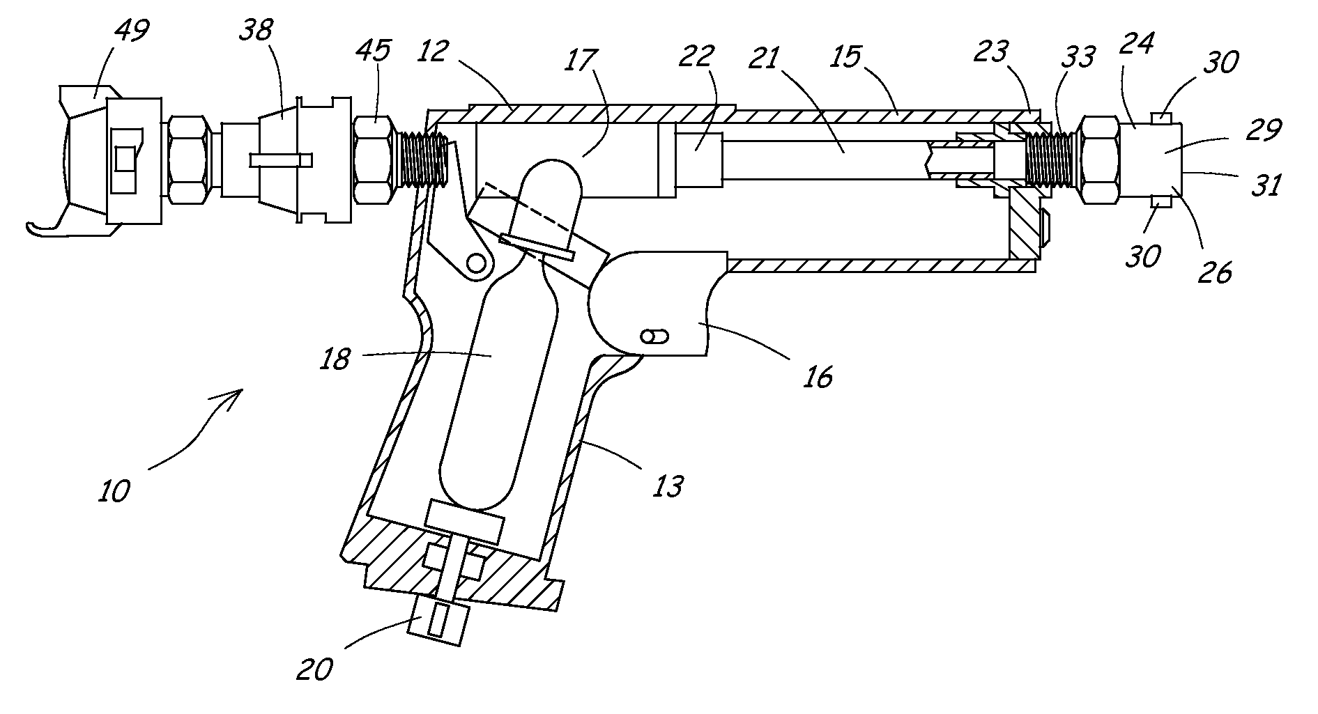
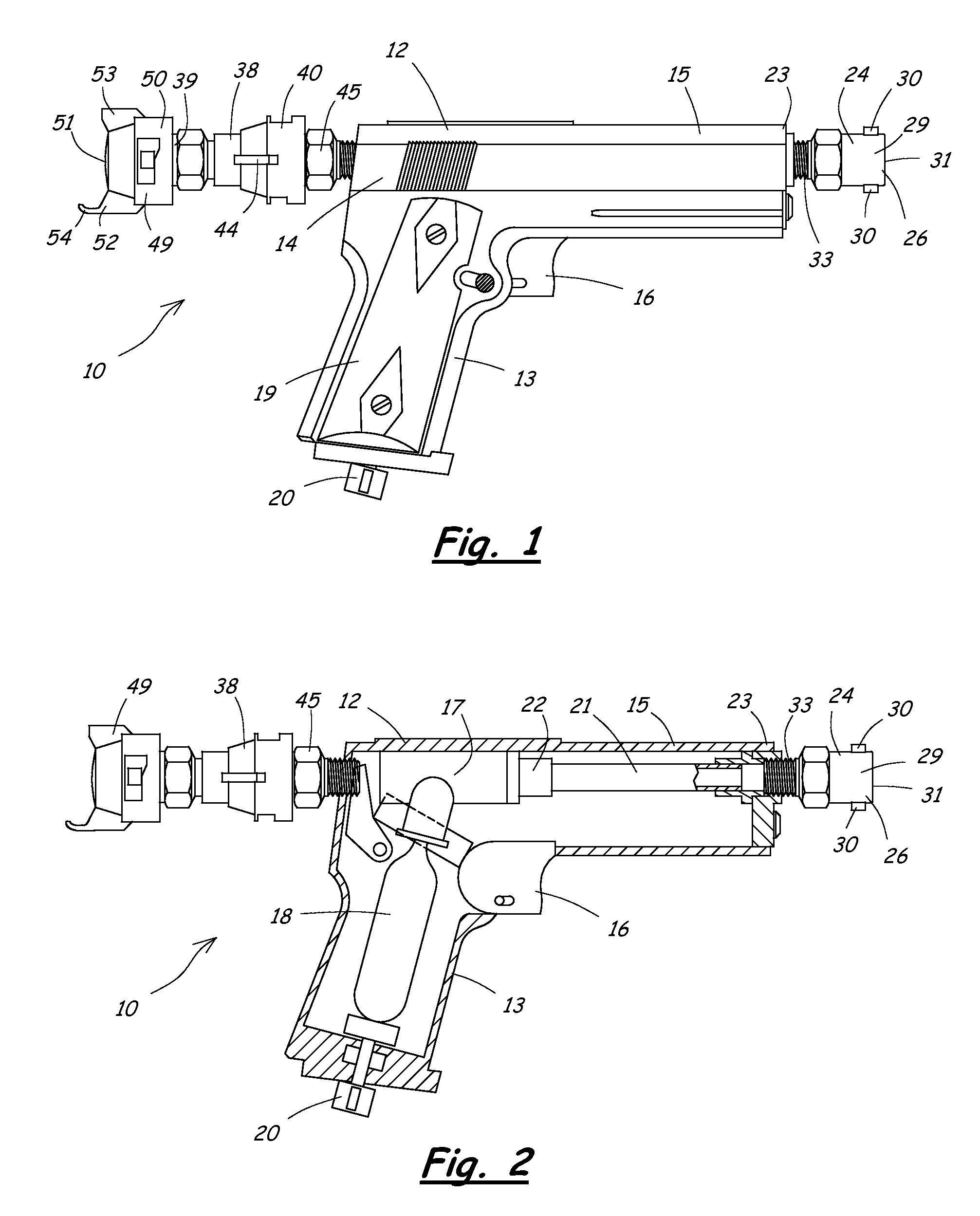
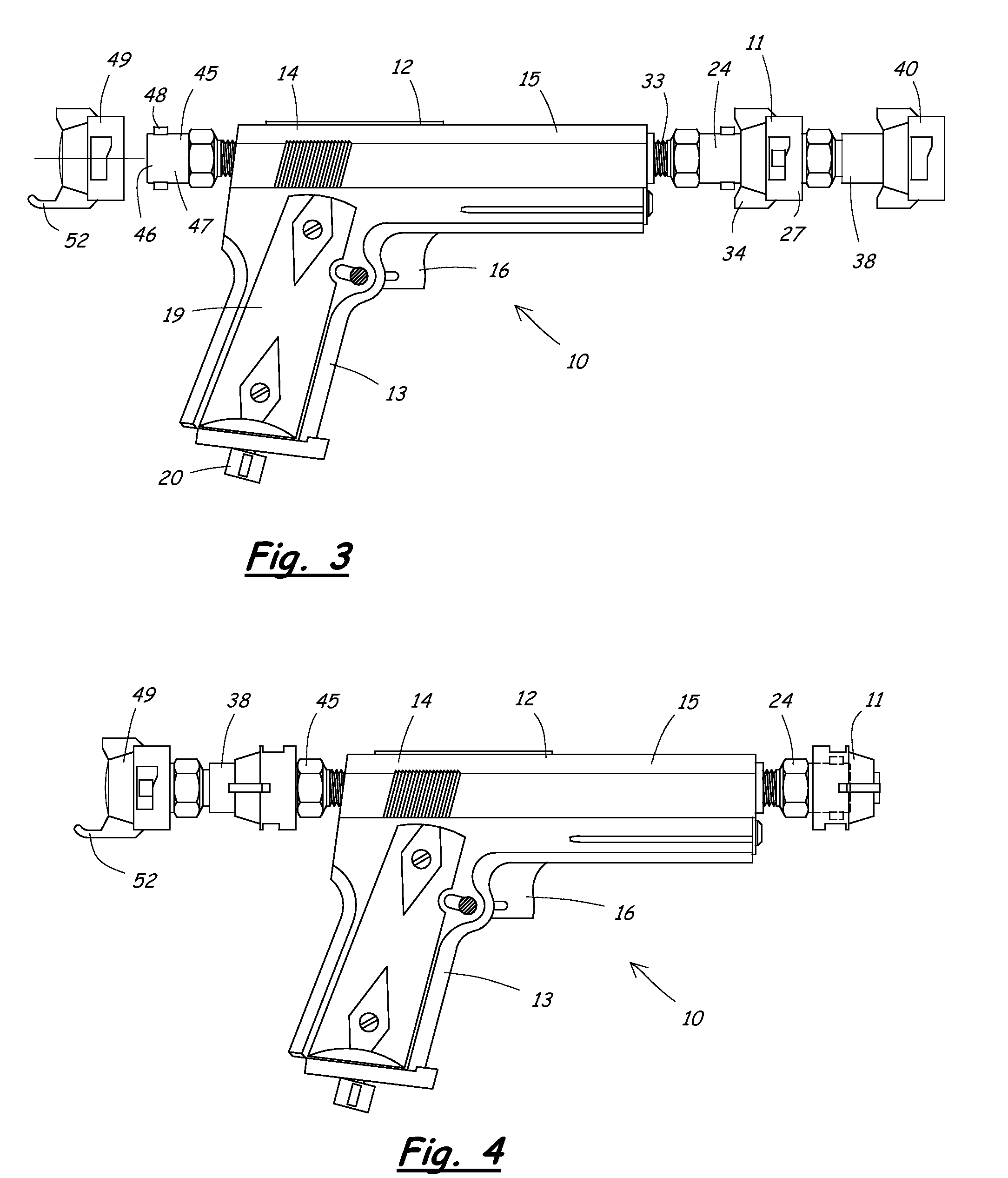
[0012]To accomplish these and other objects of the invention, a handheld device is provided for clearing obstructions from spray nozzles. The device includes a housing, a gas valve system contained within the housing, and a nozzle body attachment structure. A trigger associated with the gas valve system is operable to release a blast of compressed gas from a gas canister contained within the housing for discharge through the nozzle body attachment structure. A spray nozzle placed in contact with the nozzle body attachment structure receives the blast of compressed gas to clear obstructions from within the spray nozzle. The attachment structure interfaces with both the normal discharge side and the normal inlet side of the spray nozzle to allow compressed gas to be blown through the spray nozzle in both directions. A backup tool is provided to engage a backside of the spray nozzle to prevent the spray tip within the spray nozzle from blowing backwards out of the spray nozzle when the compressed gas is blown through the nozzle in a reverse direction of normal fluid flow. A backup tool cover prevents debris from entering the backup tool when it is not being used. The cover has a slender projection extending from one side thereof for removing screen filters associated with the spray nozzle.

Problems solved by technology

During the process of loading or filling a sprayer, dirt and other small debris often falls into the spray tank.
Mineral deposits in the water can also get into the spray tips and create obstructions.
Spray lines also tend to collect traces of chemicals that form coatings within the sprayer parts over time.
All of these types of particles can get caught in the spray tips of the spray nozzles during normal operation of the sprayer in the field.
Also, if the sprayer operator turns too fast or too close to the end of the field, the spray boom can sometimes drag on the ground and block a spray tip with dirt and mud.
Most obstructions or plugs in the spray tips occur while the operator is out in the field spraying and away from a source of clean running water and / or compressed air that could be used to clean the spray tip.
However, a razor or sharp knife will damage a spray tip if it is used too aggressively, which will result in a distorted spray pattern.
When the operator blows on a spray tip to blow out the obstruction, the operator can be exposed to harmful chemicals.
Using a small stick or piece of residue to remove the obstruction can also damage the delicate inner bore of the spray tip or break off in the spray tip and create an even bigger blockage.

Method used


Image

  • Handheld device and method for clearing obstructions from spray nozzles
  • Handheld device and method for clearing obstructions from spray nozzles
  • Handheld device and method for clearing obstructions from spray nozzles

Examples


example

[0053]A working prototype of the present invention was made by modifying a Daisy Model 93 CO2 BB pistol. The BB pistol was modified by removing several parts that were not necessary to the operation of the present invention. Specifically, the magazine, the parts that transfer BBs from the magazine to the barrel, and other nonessential parts associated with firing the BBs were removed.

[0054]A seal was then made to provide a fluid-tight connection between the rear end of the barrel tube and the gas valve system. Another seal was made to provide a fluid-tight connection between the discharge end of the barrel tube and a nozzle body attachment structure. The nozzle body attachment structure for the prototype was an existing sprayer fitting having a threaded portion at one end and a male coupler portion at the other end. The backup tool was made as shown in the drawings by modifying and assembling existing sprayer fittings suitable for the purpose.

[0055]Embodiments of the present inventi...


PUM


Abstract

A handheld device and method for clearing obstructions from spray nozzles includes a housing, a gas valve system contained within the housing, and a nozzle body attachment structure. A trigger associated with the gas valve system is operable to release a blast of compressed gas through the attachment structure. A spray nozzle placed in contact with the attachment structure receives a blast of compressed gas to clear obstructions. The attachment structure interfaces with both the normal discharge side and the normal inlet side of the spray nozzle to allow compressed gas to be blown through the spray nozzle in both directions. A backup tool is provided to engage a backside of the spray nozzle to prevent a spray tip within the spray nozzle from blowing backwards out of the spray nozzle. A backup tool cover has a slender projection for removing screen filters associated with the spray nozzle.

Description

RELATED APPLICATIONS[0001]This application claims priority of U.S. Provisional Application No. 60 / 926,095 filed on Apr. 26, 2007. The entire content of this prior application is incorporated herein by reference.BACKGROUND OF THE INVENTION[0002]1. Field of the Invention[0003]The present invention relates generally to sprayers having removable spray nozzles and, in particular, to devices and methods for clearing obstructions from the spray nozzles of such sprayers.[0004]2. Description of the Related Art[0005]Modern sprayers typically have a plurality of spray nozzles arranged along a spray boom at spaced intervals. Many different types and sizes of sprayers are available for agricultural, industrial, commercial and private uses. Modern sprayers typically use quick-attach spray nozzles that can be quickly and easily removed from the boom for servicing and then reattached. The spray nozzles typically have replaceable spray tips and inline screen filters. Quick-attach spray nozzles allow...

Claims


Application Information

Patent Timeline
Patent Type & Authority Patents(United States)
IPC IPC(8): A62C5/02A62C31/02B05B1/28B05B15/02B05B7/02F23D11/34
CPCB05B15/025B05B15/55
Inventor MARTIN, PHILLIP JOHN
Owner MARTIN PHILLIP JOHN
Learn More