Concrete form brace and battering wedge

a concrete form and wedge technology, applied in the direction of forms/shuttering/falseworks, shaping building parts, ways, etc., can solve the problems of not always dimensionally uniform, wooden blocks are typically cut into triangular shapes, and wooden blocks are usually damaged, so as to facilitate the securing of the brace and add rigidity

Active Publication Date: 2010-11-09
DAYTON SUPERIOR CORP
View PDF125 Cites 36 Cited by
  • Summary
  • Abstract
  • Description
  • Claims
  • Application Information

AI Technical Summary

Benefits of technology

[0007]The present invention provides a concrete form brace which is convenient for use in securing concrete forms in an upstanding orientation relative to a concrete casting surface. In an exemplary embodiment, the form brace has a pair of confronting sidewalls, each having a generally triangular shape. Two side edges of the sidewalls are disposed at approximately 90 degrees to one another, and a back wall extends between the sidewalls, opposite the 90 degree angle. Ribs extending between the sidewalls help to reinforce the sidewalls and add rigidity to the brace. A flange extends outwardly from the side edges of the sidewalls and the ends of the back wall, around the periphery of the brace. Apertures formed through the peripheral flange are sized to receive fasteners, such as nails, to facilitate securing the brace to the form and the casting surface. In one embodiment, the brace is formed as a unitary, molded component.

Problems solved by technology

The wooden blocks are typically saw cut into a triangular shape and are not always dimensionally uniform.
These wooden blocks are usually damaged upon removal from the concrete forms and are therefore generally not reusable.
Prior steel braces are generally reusable, but are also generally more expensive than wooden blocks, and considerably heavier, rendering them less convenient to transport and handle.

Method used


Image

  • Concrete form brace and battering wedge
  • Concrete form brace and battering wedge
  • Concrete form brace and battering wedge

Examples


Embodiment Construction

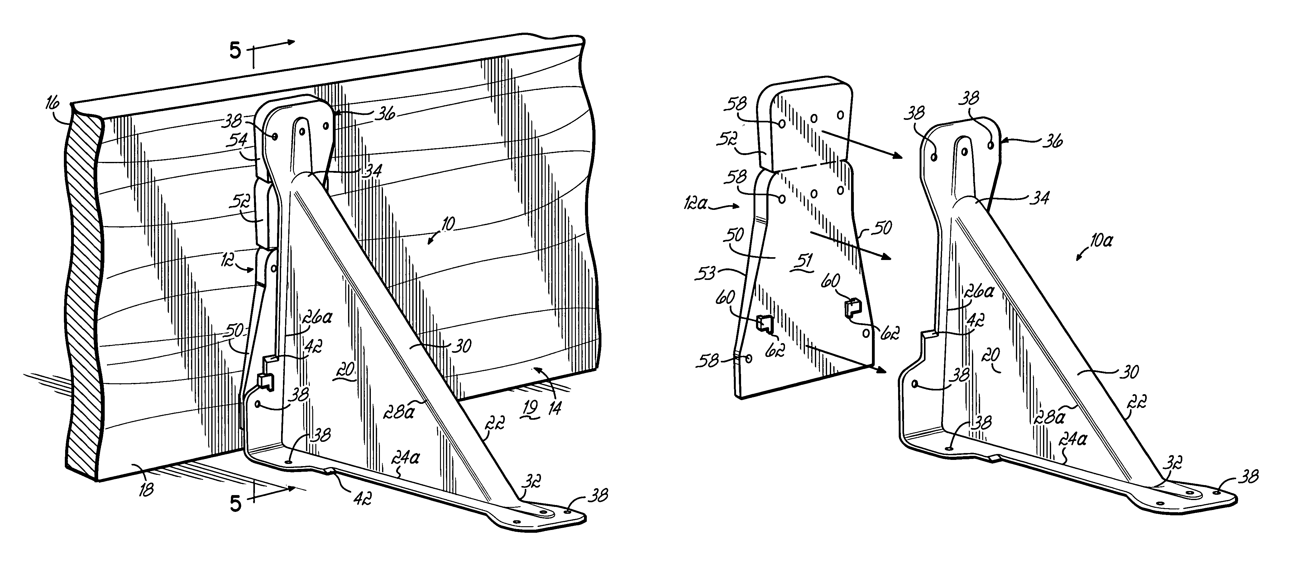
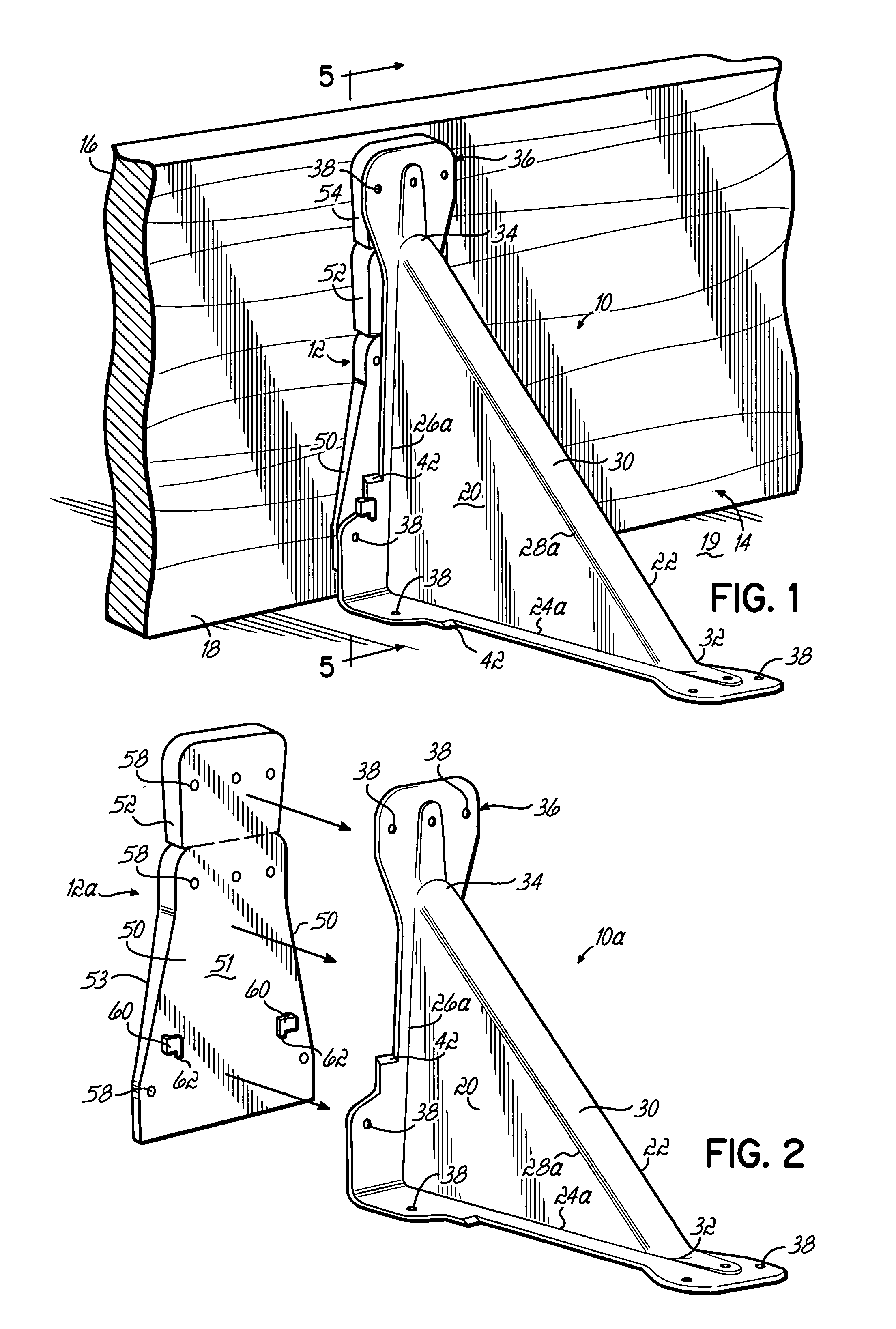
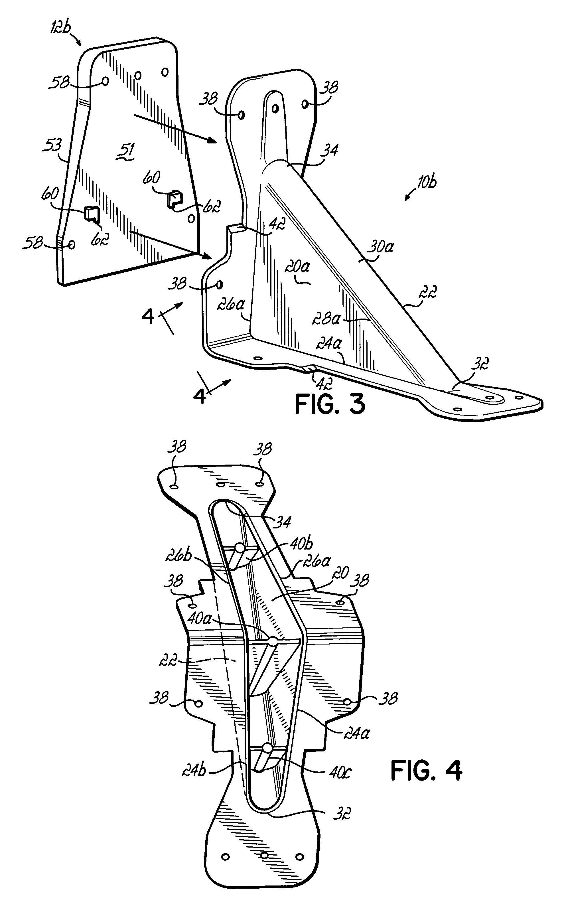
[0018]In FIG. 1, there is shown an exemplary brace 10 and battering wedge 12 according to the present invention, for supporting a concrete form member 14 in an upstanding relation to a concrete casting surface 19. The brace 10 includes first and second confronting sidewalls 20, 22 each having a generally triangular shape. First and second adjacent side edges 24a, 26a and 24b, 26b of the respective sidewalls 20, 22 are positioned to form an included angle of approximately 90 degrees. While second sidewall 22 and second side edges 24b, 26b are not visible in FIG. 1, these features are shown in FIG. 4 for a corresponding brace 10b.

[0019]A third side edge 28a, 28b of the respective sidewalls 20, 22 is disposed opposite the angle between the first and second side edges 24a, 24b, 26a, 26b. The brace 10 further includes a backwall 30 extending between the third side edges 28a, 28b of the first and second sidewalls 20, 22. The backwall 20 has a first end 32 proximate the first side edges 2...


PUM


Abstract

A brace for securing concrete forms to a base has first and second triangularly-shaped sidewalls and a back wall extending between corresponding side edges of the sidewalls. A peripheral flange extends outwardly from the side edges of the sidewalls and the ends of the back wall and has apertures for facilitating fastening of the brace to the concrete forms and a casting surface. Advantageously, the brace can be formed as a unitary, molded component. A battering wedge is selectively attachable to the side edges of the sidewalls and cooperates with the brace to facilitate tilting the concrete form at an angle to the casting surface. The battering wedge is selectively frangible to permit use with braces of varying size.

Description

[0001]This application is related to application Ser. No. 10 / 121,125, filed Apr. 11, 2002 (pending) and application Ser. No. 10 / 425,519, filed Apr. 29, 2003 (pending).FIELD OF THE INVENTION[0002]This invention pertains generally to concrete construction, and more particularly to a brace for securing concrete forms to a casting surface.BACKGROUND OF THE INVENTION[0003]Concrete wall panels are conventionally used in the construction of industrial buildings and other structures. In general, individual concrete wall panels are formed at the construction site by pouring concrete into forms which have been assembled on a casting surface, such as the floor of the building where the wall panels will be used. The concrete forms are typically secured to the casting surface by braces which hold the forms in place until the concrete wall panel has cured. The concrete forms are typically made of wood and the braces are often nailed to the forms and the casting surface. When the wall panel has cu...

Claims


Application Information

Patent Timeline
Patent Type & Authority Patents(United States)
IPC IPC(8): E04G17/14
CPCE04G13/00E04G17/14
Inventor BENNETT, CLIFFORD D.LEE, KENNETH
Owner DAYTON SUPERIOR CORP
Why Eureka
Try Eureka